6816812H01 March 23, 2006
Options and Accessories Installation: Dash-Mount Accessory Installation 3-3
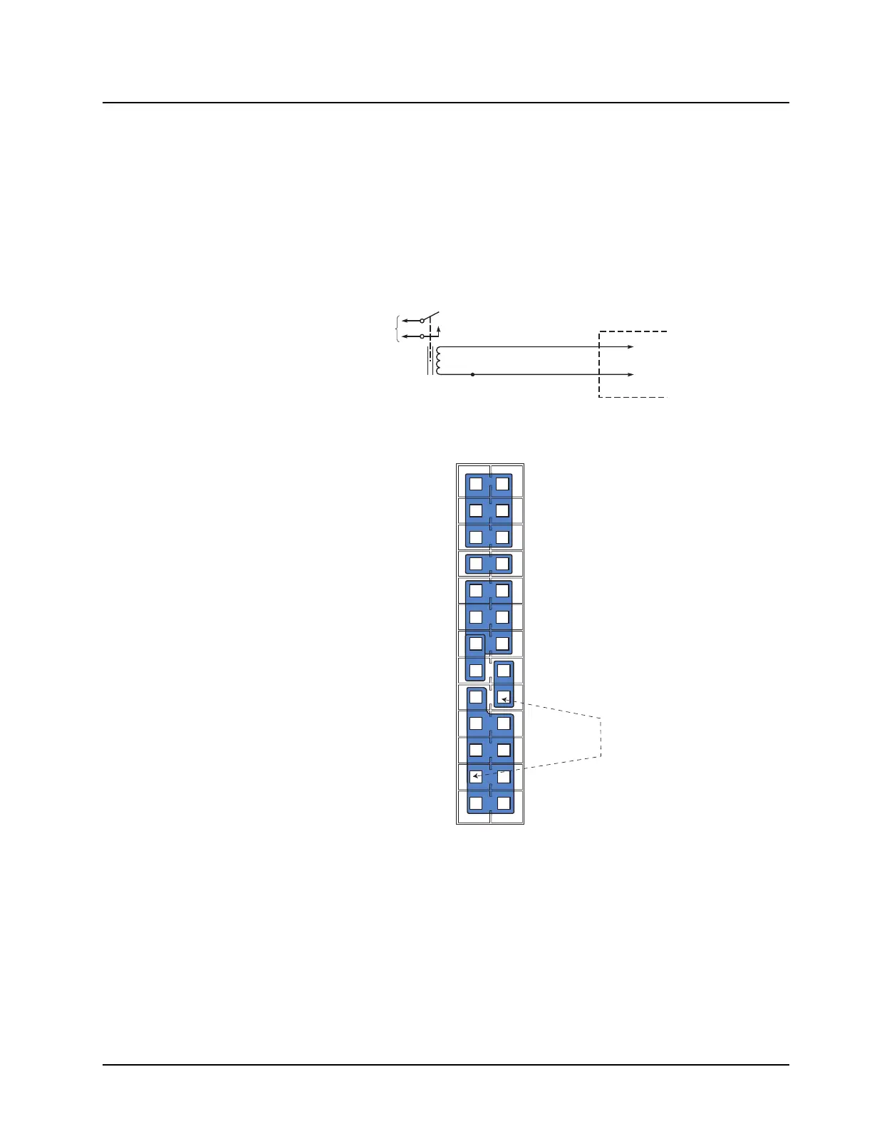
3.2.2 Horn and Lights (External Alarm) Relay
For installations that use the horn/lights option, select a suitable location for mounting (normally
under the dash) and, referring to Figure 3-3, perform the following procedure:
1. Horn Relay—Connect the relay contacts across the horn ring switch, typically found in the
steering column. Open the accessory cable connector and connect the two control wires
(male pins) into locations 26 and 7 of the connector.
2. Lights Relay—Connect the relay across the headlamp ON/OFF switch, typically found in the
steering column. Open the accessory cable connector and connect the two control wires
(male pins) into locations 26 and 7 of the accessory connector.
Figure 3-3. Horn/Light Wiring Diagram
3. Squeeze the covers together bending the wires in the strain-relief features. You may need a
pair of pliers to seat the assembly covers.
4. Once the covers are fully seated, fasten them with the cover screws. Tighten the screws
firmly but do not over-tighten them. Be sure none of the wires are pinched.
5. Reattach the accessory connector assembly to the back of the radio and fasten it by finger-
tightening the jackscrews to prevent any loosening.
CONNECT
ACROSS HORN
RING SWITCH
ND/OR HEAD LAMP SWITCH
SPST
N.O.
RELAY
12V COIL
VIP OUT 1
SWB+
ACCESSORIES
CONNECTOR
PIN 26
PIN 7
1
2
3
4
5
6
7
8
9
10
11
12
13
14
15
16
17
18
19
20
21
22
23
24
25
24
D+
Vbus
APM 2 (1-wire)
SW B+
Spkr-
Tx Audio
Aux Audio Out 1 / RxD
Aux Audio Out 2 / TxD
GP5_1 (PTT)
GP5_2 (Monitor)
GP5_3 (Chan Act)
Emerg Sw
Ign Sense
D-
USB / APM Ground
APM 1 (1-wire)
Power Ground
Spkr+
Audio Ground
Rx Audio
Ground
Ground
GP5_6
GP5_7
GP5_8
VIP_1 (Ext Alarm)
 Loading...