1-9
Getting Started
BIOS
BATT
+
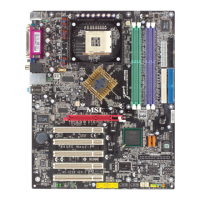
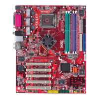
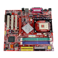
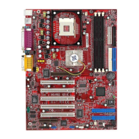
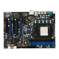
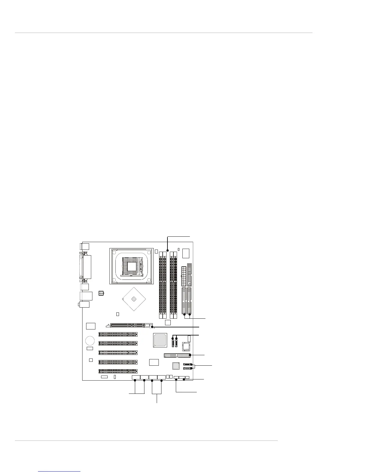
Color Management
MSI has a unified color management rule for some connectors on the
mainboards, which helps you to install the memory modules, expansion cards
and other peripherals devices more easily and conveniently.
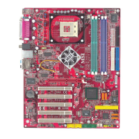
h Dual Memory DDR DIMMs: Channel A is light green, Channel B is
purple
h Intel spec IDE ATA66/100 connector: 1st IDE is blue, 2nd IDE is
white
h IDE ATA133 connector: yellow
h Serial ATA150 connector: orange
h AGP 8X slot: red
h 1394 connector: dark green
h USB 2.0 connector: yellow
h Front panel connector JFP1 : HDD LED is red, Reset Switch is blue,
Power Switch is black, Power LED is light green.
h Front panel connector JFP2: Power LED is light green.
Memory DDR DIMMs
Front Panel connector JFP2
USB 2.0 connector
AGP 8X Slot
Intel spec IDE ATA66/100 connectors:
1st IDE: blue/2nd IDE: white
Front Panel connector JFP1
1394 connectors
IDE ATA133 connector
Serial ATA150 connectors
Serial ATA150 connectors
 Loading...