 Loading...
Do you have a question about the MSI B350M PRO-VDH and is the answer not in the manual?
| Form Factor | Micro ATX |
|---|---|
| Chipset | AMD B350 |
| CPU Socket | AM4 |
| Memory Support | DDR4 |
| Memory Slots | 4 |
| Max Memory | 64 GB |
| LAN | Realtek 8111H Gigabit LAN |
| Integrated Graphics | Depends on CPU |
| RAID Support | RAID 0, 1, 10 |
| Storage Interface | 4 x SATA 6Gb/s, 1 x M.2 |
| Audio | Realtek ALC887 |
| Video Outputs | 1 x DVI-D, 1 x HDMI |
| Memory Speed | 2133/2400/2667 MHz (OC up to 3200 MHz) |
| PCIe Slots | 1 x PCIe 3.0 x16, 2 x PCIe 2.0 x1 |
| USB Ports | 4 x USB 3.1 Gen1, 6 x USB 2.0 |
Details the supported CPU types and socket compatibility.
Outlines the motherboard's chipset models.
Specifies memory slot types, capacity, and supported speeds.
Lists PCIe slots and their configurations for expansion cards.
Details integrated graphics ports and maximum supported resolutions.
Covers SATA and M.2 storage interface details and RAID support.
Information on the onboard audio codec and channel configuration.
Specifies the integrated LAN controller and its speed.
Enumerates USB port types, counts, and internal header details.
Lists all physical connectors present on the motherboard's rear I/O panel.
Details internal headers for front panel, fans, and other modules.
Identifies the specific I/O controller chip used on the motherboard.
Describes system monitoring capabilities like temperature and fan speed.
Specifies the physical dimensions and form factor type (m-ATX).
Highlights key BIOS features including flash size, version, and multi-language support.
Lists bundled software utilities for system management and enhancement.
Explains the status and speed indicators for the LAN port LEDs.
Step-by-step guide to configuring the 7.1-channel audio output.
Identifies the location and purpose of the CPU socket.
Indicates the slots for installing RAM modules.
Shows the layout and types of PCIe expansion slots.
Locates the front panel connectors for power/reset switches and LEDs.
Identifies the SATA ports for connecting storage devices.
Shows the location of the M.2 slot for SSDs.
Locates the main ATX and CPU power connectors.
Identifies the internal USB 2.0 headers.
Locates the internal USB 3.1 Gen1 header.
Points out the fan headers for CPU and system cooling.
Locates the connector for a Trusted Platform Module.
Identifies the connector for chassis intrusion detection.
Locates the front panel audio header.
Identifies the serial port connector.
Locates the parallel port connector.
Shows the location of the CMOS reset jumper.
Points out the EZ Debug LEDs for troubleshooting.
Locates the connector for RGB LED strips.
Step-by-step instructions for installing a CPU into the motherboard socket.
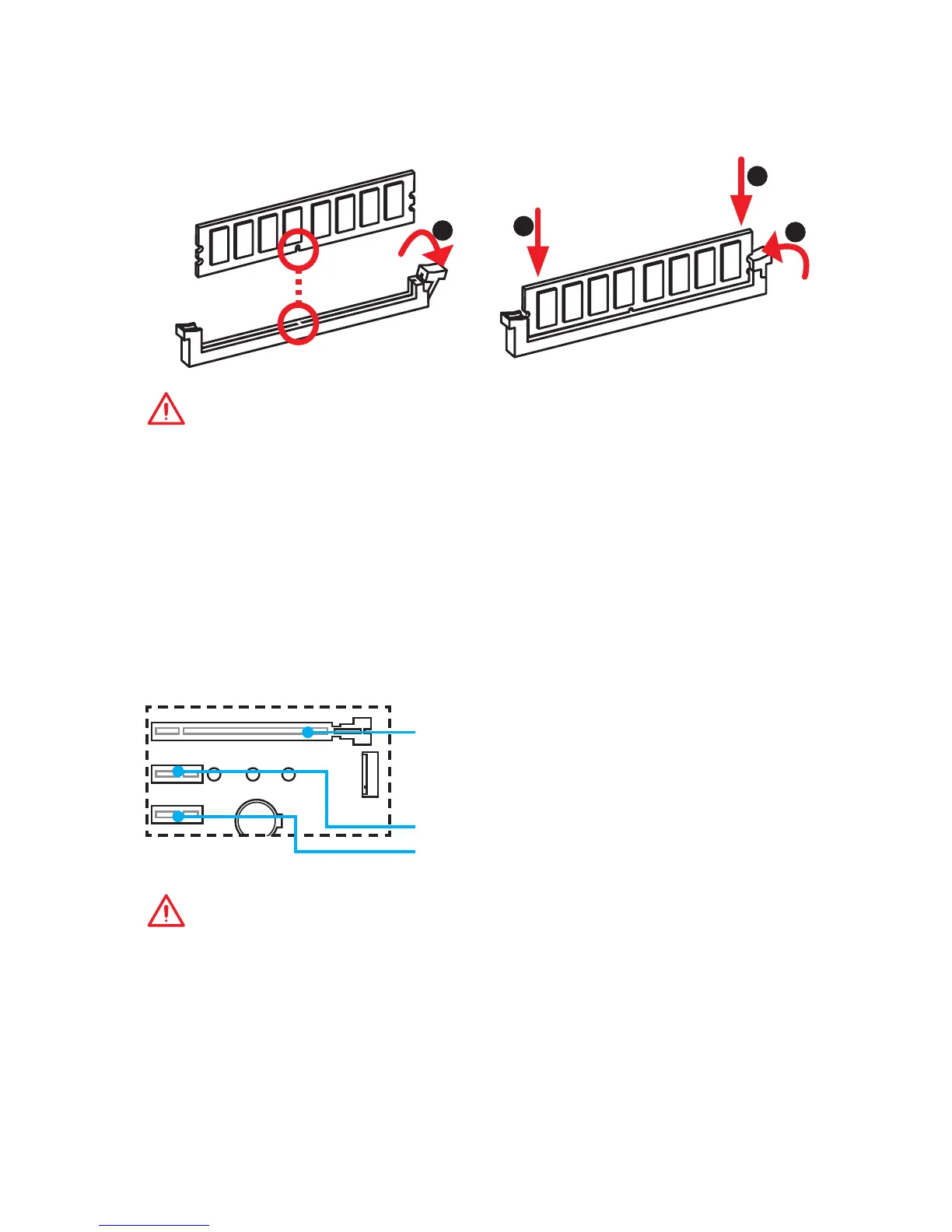
Guide on how to properly install memory modules into the DIMM slots.
Information and precautions for installing expansion cards in PCIe slots.
Details on connecting front panel switches, LEDs, and audio.
Information and handling recommendations for SATA connectors.
Instructions for installing an M.2 SSD into the designated slot.
Pinout and connection details for ATX and CPU power connectors.
Pinout details for connecting USB 2.0 devices to the front panel.
Pinout details for connecting USB 3.1 Gen1 devices to the front panel.
Explanation of PWM and DC fan connector modes and pin definitions.
Details the connector for a Trusted Platform Module (TPM).
Explains the chassis intrusion connector and its detection function.
Pinout details for the front panel audio connector (JAUD1).
Pinout details for the optional serial port connector (JCOM1).
Pinout details for the optional parallel port connector (JLPT1).
Instructions for resetting BIOS settings using the JBAT1 jumper.
Explanation of the EZ Debug LEDs for system status and troubleshooting.
Details on connecting and controlling RGB LED strips.
Instructions on how to access the BIOS setup menu during boot.
Methods for restoring BIOS settings to default values.
Procedures for updating the BIOS using M-FLASH or Live Update 6.
Guide for installing Windows 7 or Windows 10 operating systems.
Instructions for installing essential motherboard drivers.
Steps for installing supplementary software utilities.