EasyManuals Logo
Home>MSI>Motherboard>B75A-G43 series

MSI B75A-G43 series User Manual

MSI B75A-G43 series
37 pages
To Next Page IconTo Next Page
To Previous Page IconTo Previous Page
Page #21 background imageLoading...
Page #21 background image
En-20
MS-7758 Manboard
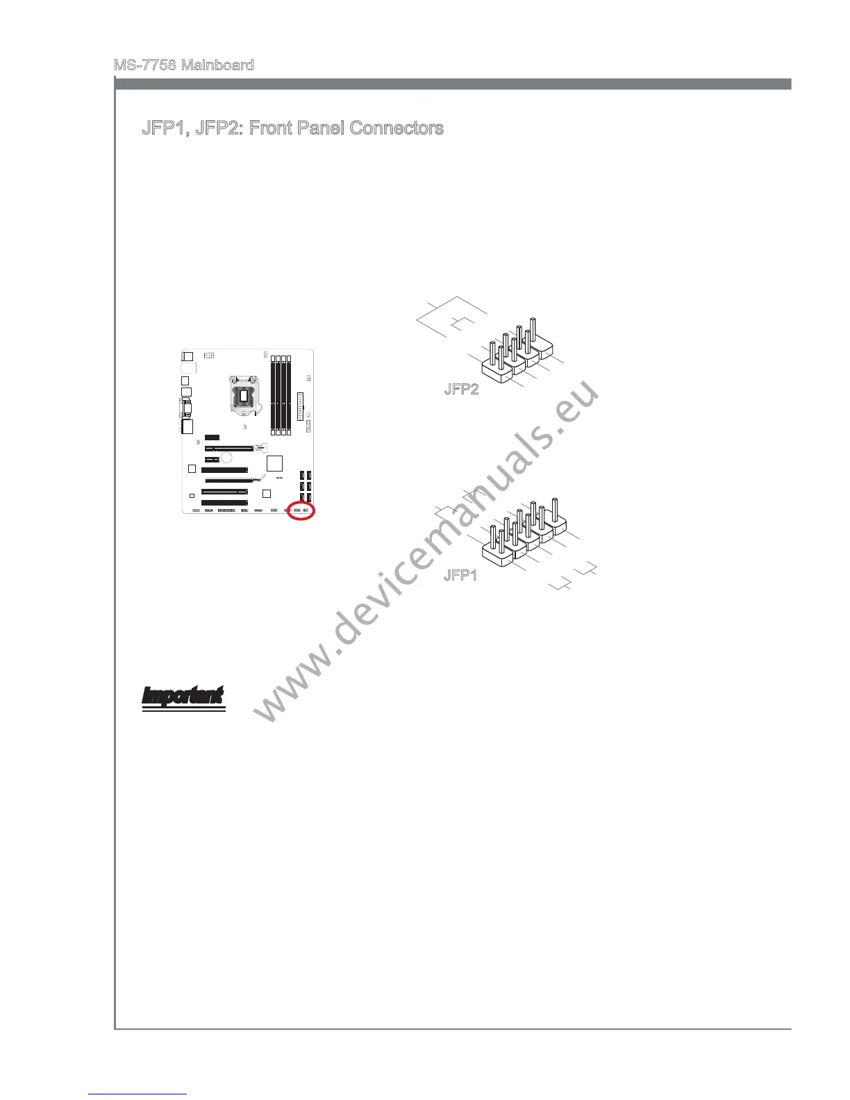
JFP1, JFP2: Front Panel Connectors
These connectors connect to the front panel swtches and LEDs. The JFP1 connector s
complant wth the Intel
®
Front Panel I/O Connectvty Desgn Gude. When nstallng the
front panel connectors, please use the enclosed mConnectors to smplfy nstallaton.
Plug all the wres from the computer case nto the mConnectors and then plug the
mConnectors nto the manboard.
1.+
3.-
10.No Pin
5.-
Reset Switch
HDD LED
Power Switch
Power LED
7.+
9.Reserved
8.-
6.+
4.-
2.+
JFP1
1.Ground
3.Suspend LED
5.Power LED
7.No Pin
8.+
6.-
4.+
2.-
Buzzer
Speaker
JFP2
Important
On the connectors comng from the case, pns marked by small trangles are postve
wres. Please use the dagrams above and the wrtng on the mConnectors to
determne correct connector orentaton and placement.
The majorty of the computer case’s front panel connectors wll prmarly be plugged
nto JFP1.
www.devicemanuals.eu

Questions and Answers:

Question and Answer IconNeed help?

Do you have a question about the MSI B75A-G43 series and is the answer not in the manual?

MSI B75A-G43 series Specifications

General IconGeneral
BrandMSI
ModelB75A-G43 series
CategoryMotherboard
LanguageEnglish

Related product manuals