11
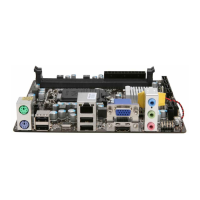
PCI_E1~2: PCIe Expansion Slots
PCI_E1: PCIe 4.0 x16 (From CPU)
PCI_E2: PCIe 3.0 x1 (From B660/ H610 chipset)
Important
If you install a large and heavy graphics card, you need to use a tool such as MSI
Graphics Card Bolster to support its weight to prevent deformation of the slot.
When adding or removing expansion cards, always turn off the power supply and
unplug the power supply power cable from the power outlet. Read the expansion
card’s documentation to check for any necessary additional hardware or software
changes.
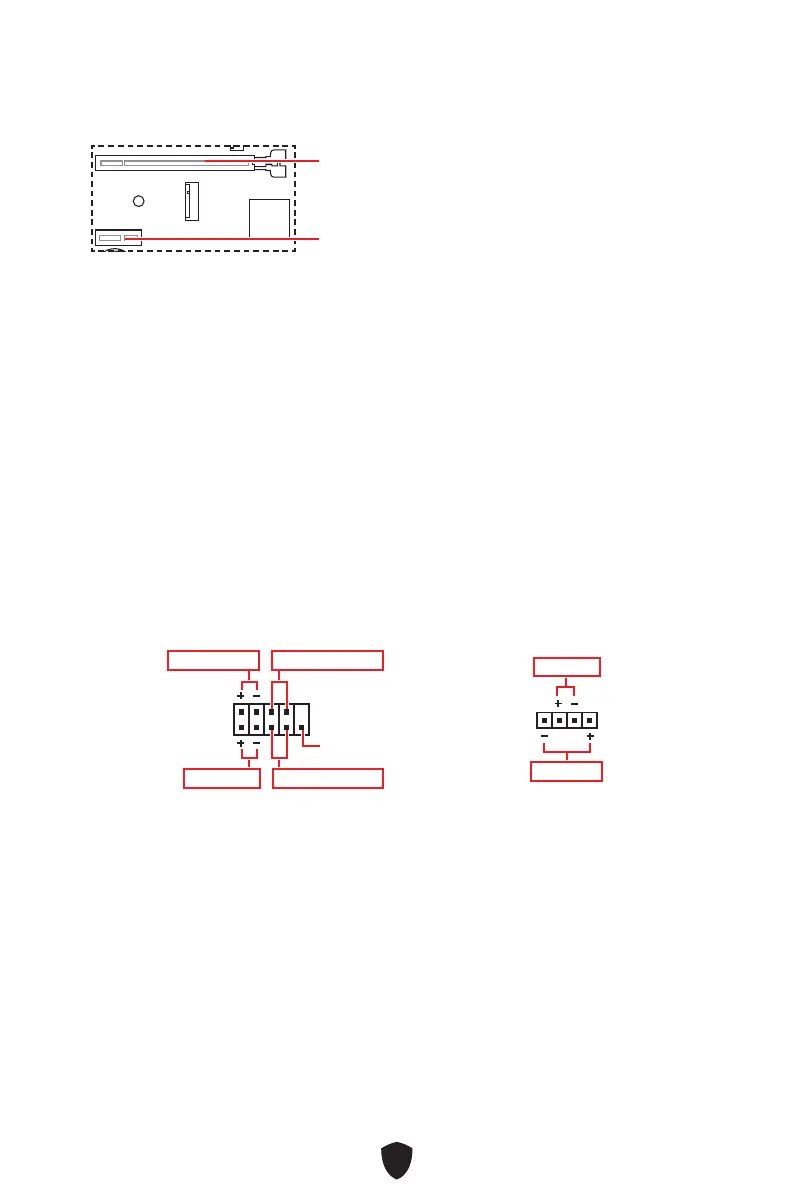
JFP1, JFP2: Front Panel Connectors
The JFP1 connector controls the power on, power reset, and the LEDs on your PC
case/chassis. Power Switch/ Reset Switch headers allow you to connect power button/
reset button. Power LED header connects to LED light on the PC case, and HDD LED
header indicates the activity of the hard disk. The JFP2 connector is for Buzzer and
Speaker. To connect the cables from PC case to the right pins, please refer to the
following images below.
1
2 10
9
Power LED
Reserved
Power Switch
JFP1
Reset SwitchHDD LED
1
JFP2
Buzzer
Speaker
Important
Please note that Power LED and HDD LED have positive and negative connection,
you need to link up the cable to the corresponding positive and negative port on the
motherboard. Otherwise, LEDs won’t work properly.
 Loading...