17
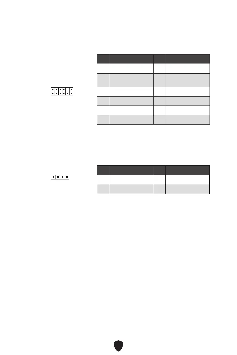
JTPM1: TPM Module Connector
This connector is for TPM (Trusted Platform Module). Please refer to the TPM security
platform manual for more details and usages.
Pin Signal Name Pin Signal Name
1 SPI Power 2 SPI Chip Select
3
Master In Slave Out
(SPI Data)
4
Master Out Slave In
(SPI Data)
5 Reserved 6 SPI Clock
7 Ground 8 SPI Reset
9 Reserved 10 No Pin
11 Reserved 12 Interrupt Request
1
2 12
11
Important
The JRGB connector supports up to 2 meters continuous 5050 RGB LED strips
(12V/G/R/B) with the maximum power rating of 3A (12V).
Always turn off the power supply and unplug the power cord from the power outlet
before installing or removing the RGB LED strip.
Please use MSI’s software to control the extended LED strip.
JRGB1: RGB LED connector (For PRO H610M-G DDR4)
The JRGB connector allows you to connect the 5050 RGB LED strips 12V.
Pin Signal Name Pin Signal Name
1 +12V 2 G
3 R 4 B
1
 Loading...