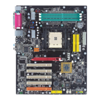
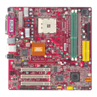
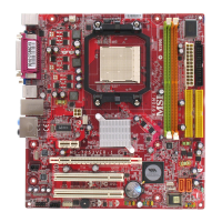
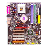
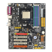
MS-7125 M-ATX Mainboard
E-2-18
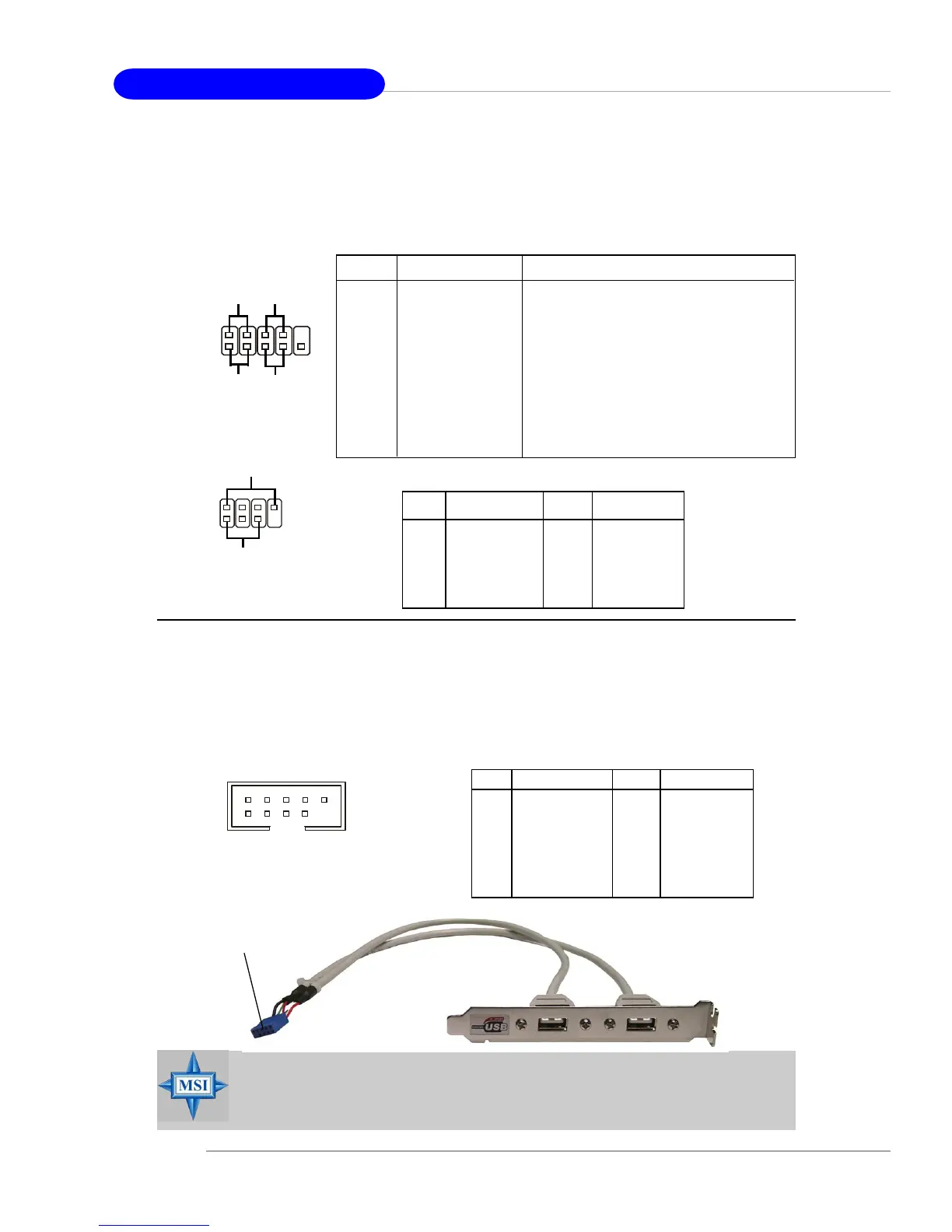
Front Panel Connectors: JFP1 / JFP2
The mainboard provides two front panel connectors for electrical connection
to the front panel switches and LEDs. JFP1 is compliant with Intel
®
Front Panel I/O
Connectivity Design Guide.
Front USB Connectors: JUSB1 / JUSB2 / JUSB3
The mainboard provides three standard USB 2.0 pin headers JUSB1 & JUSB2
& JUSB3. USB 2.0 technology increases data transfer rate up to a maximum throughput
of 480Mbps, which is 40 times faster than USB 1.1, and is ideal for connecting high-
speed USB interface peripherals such as USB HDD, digital cameras, MP3 players,
printers, modems and the like.
MSI Reminds You...
Note that the pins of VCC and GND must be connected correctly, or it
may cause some damage.
7
8
Power
LED
Speaker
1
2
JFP2
JFP1
1
9
10
2
Power
LED
Power
Switch
Reset
Switch
HDD
LED
PIN SIGNAL DESCRIPTION
1 HD_LED_P Hard disk LED pull-up
2 FP PWR/SLP MSG LED pull-up
3 HD_LED_N Hard disk active LED
4 FP PWR/SLP MSG LED pull-up
5 RST_SW_N Reset Switch low reference pull-down to GND
6 PWR_SW_P Power Switch high reference pull-up
7 RST_SW_P Reset Switch high reference pull-up
8 PWR_SW_N Power Switch low reference pull-down to GND
9 RSVD_DNU Reserved. Do not use.
JFP1 Pin Definition
PIN SIGNAL PIN SIGNAL
1 GND 2 SPK-
3 SLED 4 BUZ+
5 PLED 6 BUZ-
7 NC 8 SPK+
JFP2 Pin Definition
PIN SIGNAL PIN SIGNAL
1 VCC 2 VCC
3 USB0- 4 USB1-
5 USB0+ 6 USB1+
7 GND 8 GND
9 Key (no pin) 10 USBOC
JUSB1 & JUSB2 & JUSB3 Pin Definition
JUSB1, JUSB2, JUSB3
(USB 2.0)
1
2 10
9
Connected to JUSB1, JUSB2, or
JUSB3 (the USB pinheader in
YELLOW color)
USB 2.0 Bracket
(Optional)
 Loading...