2-19
Hardware Setup
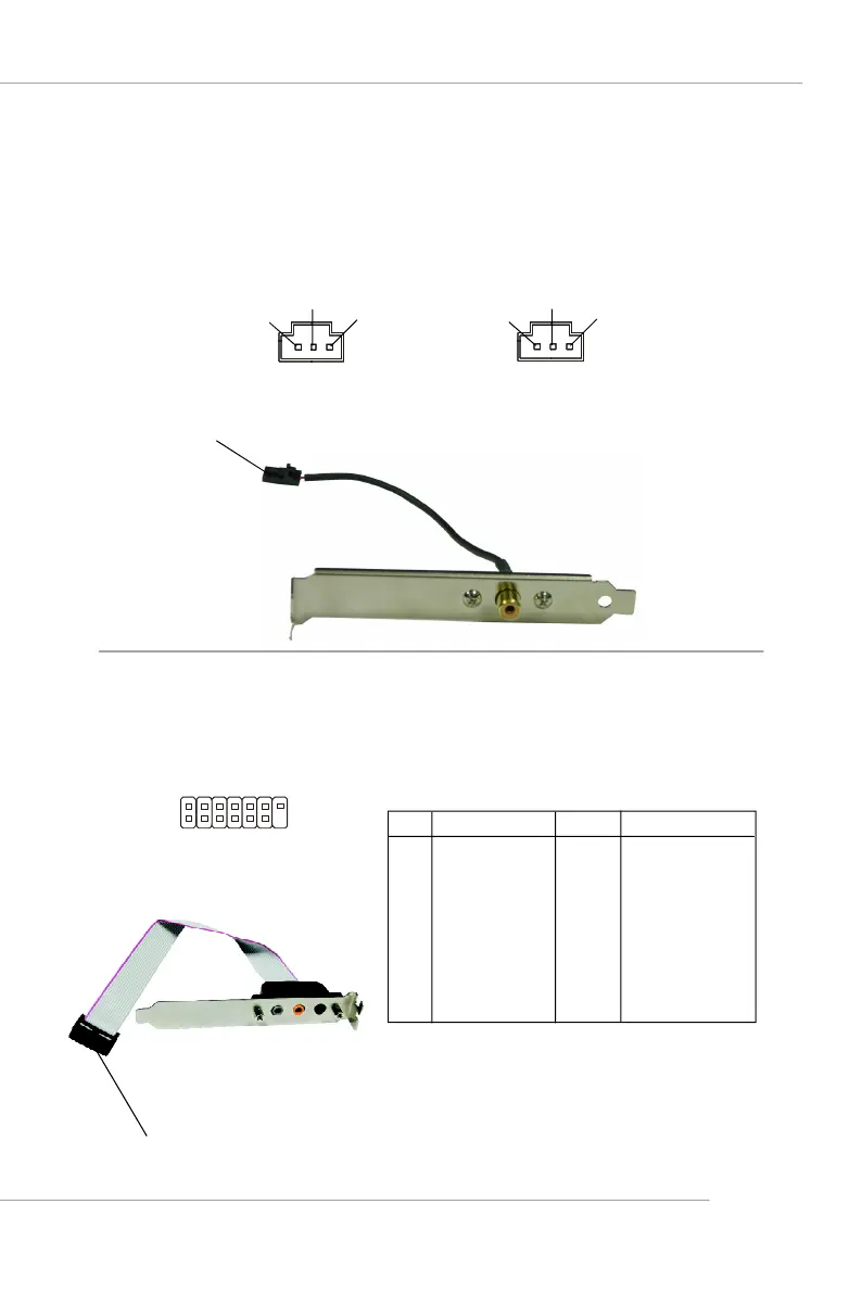
SPDIF-Out/ SPDIF-In Connector: SPDOUT/ SPDIN
These connectors are used to connect SPDIF (Sony & Philips Digital Intercon-
nect Format) interface for digital audio transmission. The JSPD1 is for SPDIF-Out and
the JSPD2 is for SPDIF-In.
Connected to SPDOUT or SPDIn is by your desire.
SPDIF Bracket (Optional)
SPDOUT
SPDIN
NC
SPDIF-Out
GND
NC
SPDIF-In
GND
Audio-out Connector: J1
The mainboard optionally provides a audio-out connector for you to attach a
Audio-Out bracket. The Audio-Out bracket offers three audio-out jacks. Select the
appropriate one to connect to the proper speaker.
Pin Definition
PIN SIGNAL PIN SIGNAL
1 LEFOut 2 SURROutR
3 CENTEROut 4 SURROutL
5 SURRBackR 6 SURRJD
7 SURRBackL 8 CENJD
9 SURRBackJD 10 Ground
11 Ground 12 Ground
13 NC 14 Ground
1
2
13
14
Connected to J1.
J1
Audio-out Bracket
(Optional)
 Loading...