48
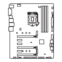
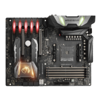
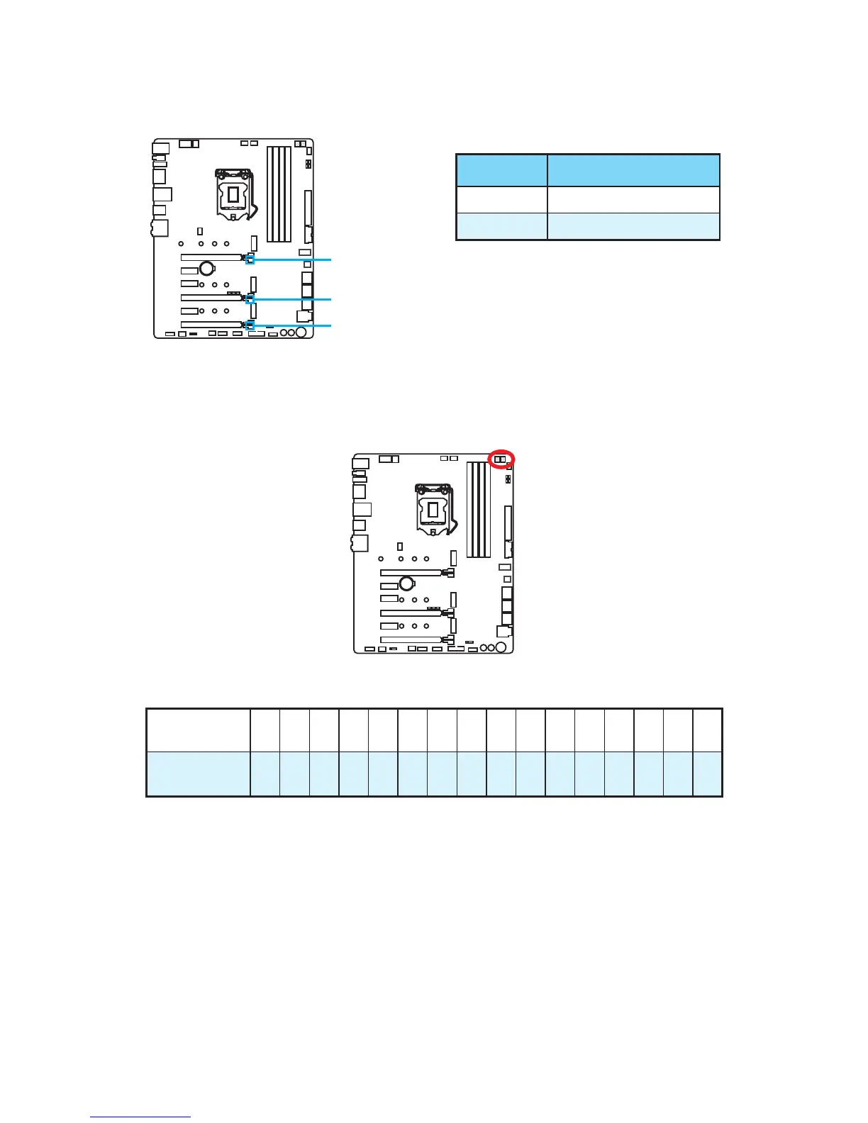
Onboard LEDs
PCI_E1 LED
PCI_E4 LED
PCI_E6 LED
PCIe x16 slot LEDs
These LED indicate the PCIe x16 slots status.
LED Color PCIe slot speed status
Red x16
White x8, x4, x1
Debug Code LED
The Debug Code LED displays progress and error codes during and after POST. Refer
to the Debug Code LED table for details.
Hexadecimal Character Table
Hexadecimal 0 1 2 3 4 5 6 7 8 9 A B C D E F
Debug Code
LED display
0 1 2 3 4 5 6 7 8 9 A B C D E F
Boot Phases
Security (SEC) – initial low-level initialization
Pre-EFI Initialization (PEI) – memory initialization
Driver Execution Environment (DXE) – main hardware initialization
Boot Device Selection (BDS) – system setup, pre-OS user interface & selecting a
bootable device (CD/DVD, HDD, USB, Network, Shell, …)
 Loading...