I 20 I
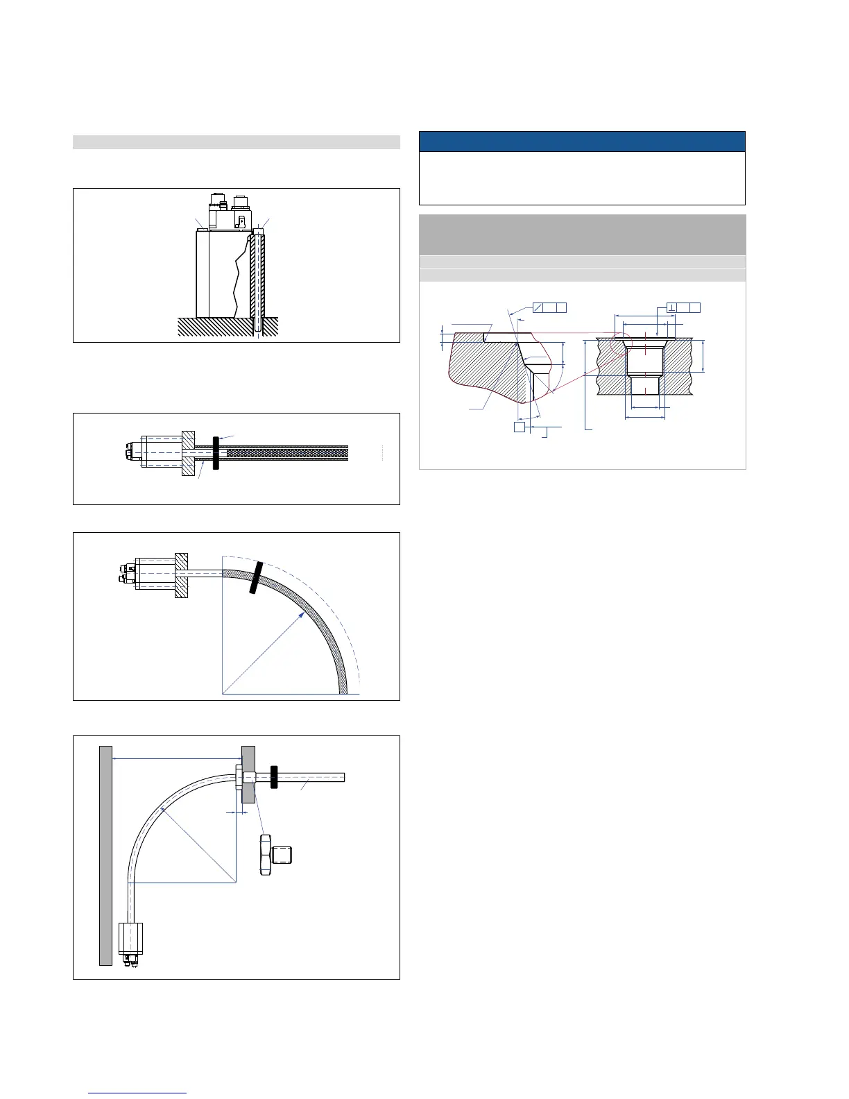
Fig. 43: Threaded flange M18×1.5 based on DIN ISO 6149-1
Fig. 39: Mounting screw M4×59
Fig. 40: Linear measurement
Fig. 41: Minimum bending radius
Fig. 42: Mounting example for distances
4.5.2 Installation of RF
Mounting of sensor electronics housing requires the use of
2 non-magnetizable screws M4×59.
NOTICE
A flexible sensor requires supports or anchoring to maintain proper
alignment between sensor rod and the magnet, otherwise the
sensor output signal can be interfered or lost.
Curvilinear measurements
Long sensors require a support tube (inner diameter of 9.4 mm
(0.37 in.)) of non-magnetizable material, straight or bent to the desired
For easy installation the sensor is supplied with a hex 46 flange (ac-
cessory) bored for above mounting screws.
Information about the mounting of the optinal accessories see:
• optional profile product brief 551 442
• optional rod with flange product brief 551 770
Thread
(d
1
×P)
d
2
d
3
d
4
d
5
L
1
L
2
L
3
L
4
Z°
M18×1.5 55 mm 13 mm 24.5 mm 19.8 mm 2.4 mm 28.5 mm 2 mm 26 mm 15°
3/4x16 See Appendix B
This dimension applies
when tap drill cannot
pass through entire boss
Thread (d
1
×P)
(Reference size)
Applies at Ød
4
A
R 0.4 max.
L
3
L
1
45° ±5°
Ra 3.2
Ød
5
Ra 3.2
Ød
2
Ra 0.2
Ra 0.1
Pitch diameter
Z°
L
2
L
4
A
0.2 A0.2 A
Ød
3
Controlling design dimensions are always in metric units and measurements in ( ) are in inches
> 250
(> 9.84)
Internal hexagon
M4×59
Internal hexagon
M4×59
500 (19.69) recommended
≥ 300 (≥ 11.8) minimum
Magnet
10
(0.39)
AF46
Flange M18×1.5 or 3/4“-16
Stainless steel 1.4305 for
rod 12.7 (0.5) AD
Part no. 402 704 (M18)
Part no. 402 641 (3/4“-16)
Customized support tube
required, inside Ø 9.4 mm
non-magnetic
e.g. Ø 12.7 × 1.65 mm
> 250
(> 9.84)
Position magnet
Non-magnetizable support tube, inner-Ø 9.4 (0.37)

 Loading...