R-Series Models RP and RH Temposonics
®
Linear-Position Sensors - SSI Output
Product Data Sheet, Part No.: 550989 E (EN) 05/2014
MTS Sensors
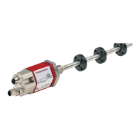
R-Series Models RP and RH Sensors
How to Order
13
SENSOR MODEL
=
R
1-2
RP =
Profile style
= Hydraulic rod style
HOUSING STYLE
=
3
Model RP profile-style sensor (includes one magnet):
S =
Captive-sliding magnet with ball
joint at top (part no. 252182)
Captive-sliding magnet with ball
joint at front (part no. 252184)
Open-ring magnet
(Part no. 251416-2)
Model RH rod-style sensor (magnet(s) must be ordered separately):
T = US customary threads, raised-faced
flange and pressure tube, standard
Same as option ‘T’, except uses
fluoroelastomer seals for the
electronics housing
Sensor cartridge only (no flange
and pressure tube, stroke length
< 1830 mm (72 in.))
S = US customary threads, flat-faced
flange and pressure tube, standard
Same as option ‘S’, except uses
fluoroelastomer seals for the
electronics housing
M = Metric threads, flat-faced flange and
pressure tube, standard
Same as option ‘M’, except uses
fluoroelastomer seals for the
electronics housing
STROKE LENGTH
4-8
— — — —
M
Millimeters
(Encode in 5 mm increments)
Stroke Length Notes:
— — — . —
U
Inches and tenths
(Encode in 0.1 in. incre-
ments)
1. Profile-style sensor (model RP) stroke range = 25 mm (1 in.) - 5080 mm. (200 in.)
2. Rod-style sensor (model RH) stroke range = 25 mm (1 in.) - 7620 mm (300 in.
CONNECTION TYPE =
9-11
Integral connector:
D70
7-pin DIN (M16), male, standard
MS0
10-Pin MS style, male
Integral cables:
P
— —
Integral high-performance cable, orange jacket with pigtail termination
Cable Length Note:
E
— —
Integral cable, PVC jacket, pigtail termination, standard
MTS recommends the maximum integral
cable length to be 10 meters (33 ft.). Cables
greater than 10 m (33 ft.) in length are available,
however, proper care must be taken during
handling and installation.
F
— —
Integral cable, black polyurethane jacket with pigtail termination
Cable length:
Encode in feet if using US customary stroke length
Encode in meters if using metric stroke length
>
— —
=
3 (03) to 98 (98) ft. or 1 (01) to 30 (30) meters.
INPUT VOLTAGE =
12
1 = +24 Vdc (+20% - 15%)
HVR Option Note:
A = Same as option “1” except includes the High
Vibration-Resistant (HVR) option for Model
RH only, limited to stroke range = 25 mm
(1 in.) - 2000 mm (78.7 in.), Refer to ‘HVR
Option Note’.
The High Vibration-Resistant (HVR) option provides the model RH rod-style
sensors with increased resistance to shock and vibration for use in heavy
duty machinery. Refer to “G-Series and R-Series Sensors for High Shock and
Vibration Applications”, document part no.: 551073 for more information.
S + the 6 digit Output code defined (Continue to the next page)
OPTIONAL ADVANCED OUTPUTS (18- 22)
99 + the 3 digit Output code defined (Continue to the next page)
R S
 Loading...


