R-Series Models RP and RH Temposonics
®
Linear-Position Sensors - SSI Output
Product Data Sheet, Part No.: 550989 E (EN) 05/2014
MTS Sensors
5
R-Series SSI Sensors, Measuring Modes
Enhanced, Monitoring Diagnostics, Field Programming
PEAK REDUCTION FILTER
A variation of the filter function is the Weighted Infinite Average (WIA) filter. If needed, this filter can provide a greater smoothing effect and
has an adjustable weight parameter.
TEMPERATURE MONITORING
A temperature monitoring device is included inside the sensor electronics housing. Its output can be used to track the general operating
conditions for the sensor and to monitor for over temperature. It cannot be used for calculating temperature compensation.
Enhanced monitoring and diagnostics
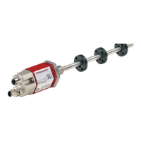
SENSOR STATUS AND DIAGNOSTIC DISPLAY
Diagnostic LEDs (green/red), located beside the connector or cable
exit (see ‘Figure 6’), provide basic visual monitoring for normal sen-
sor operation and troubleshooting. Diagnostic display LEDs indicate
four modes described in ‘Table 1’.
Figure 6. R-Series sensor Integrated diagnostic LEDs
Advanced communication and programmability
SENSOR FIELD PROGRAMMING FIELD PROGRAMMABLE PARAMETERS:
• Data length
• Data format
• Resolution
• Measuring direction
• Synchronous / asynchronous measurement
• Measurement filter
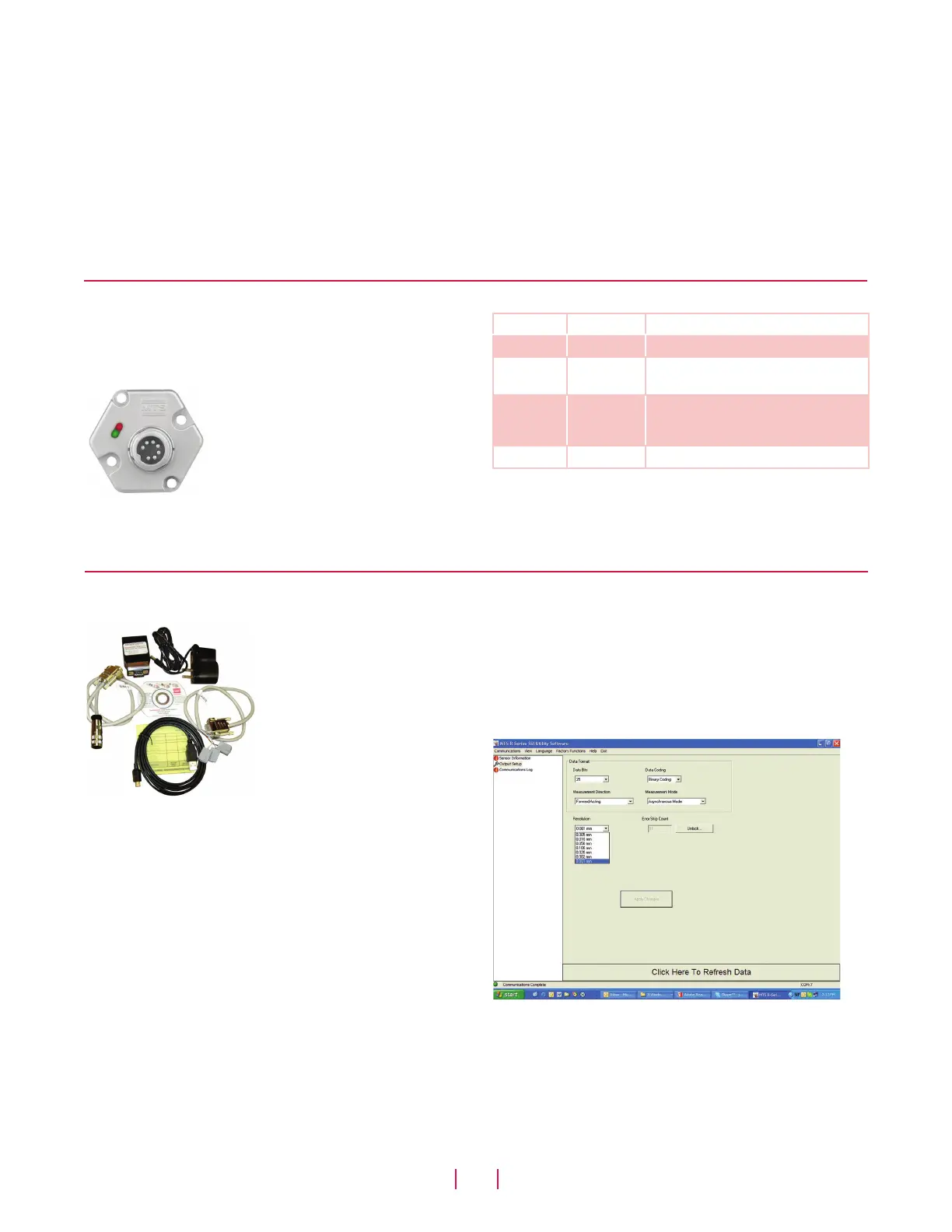
Figure 8. R-Series SSI PC Setup software interface
Green Red Operation status/mode
ON OFF Normal function (operation mode)
ON ON Magnet not detected or wrong
quantity of magnets
ON Flashing
Sensor not synchronous
(For synchronous measurement mode
only)
Flashing ON Programming mode
Table 1. Diagnostic display indicator modes
Temposonics R-Series sensors with
SSI are pre configured at the factory
by model number designation. In
the event that sensor parameter
changes are required in the field,
the ‘R-Series SSI PC Programming
Kit, part no. 253310-1’ (see ‘Figure
7) can be used to easily program the
sensor electronically without open-
ing the sensor's housing.
Figure 7. R-Series SSI PC Programming Kit, Part no. 253310-1
R-SERIES SSI PC PROGRAMMING KIT (PART NO.: 253310-1)
INCLUDES THE FOLLOWING COMPONENTS:
• Wall adapter style power supply (24 Vdc output).
• USB Serial converter box with USB cable to connect to PC
• Two connection cables:
- Cable with connector if sensor is ordered with the D70
integral connector option.
- Cable with quick connects if sensor is ordered with the
integral cable option.
• R-Series SSI PC Setup software, on CD-ROM (for Windows
XP or higher)
The Utility software included in the R-Series SSI PC Setup software
provides a user-friendly interface (see ‘Figure 8’).
The setup software allows the following set of parameters to be field
programmed.
 Loading...


