R-Series Models RP and RH Temposonics
®
Linear-Position Sensors - SSI Output
Product Data Sheet, Part No.: 550989 Revision E (EN) 05/2014 MTS Sensors4
R-Series SSI Measuring Modes
SYNCHRONOUS MEASURING MODE ('SYNC 1' OPTION)
Using the Synchronous Measuring Mode, the Temposonics SSI sensor has timing capabilities to optimize the communication link to the
controller. Many motion control applications require velocity and/or acceleration be calculated, and therefore, must rely on position data
having minimal delay, and minimal timing variability. With the Synchronous Measuring Mode, MTS Sensors has developed a proprietary
algorithm to not only guarantee true measurement synchronization but at the same time minimize any propagation delay relative to the
controller loop rate.
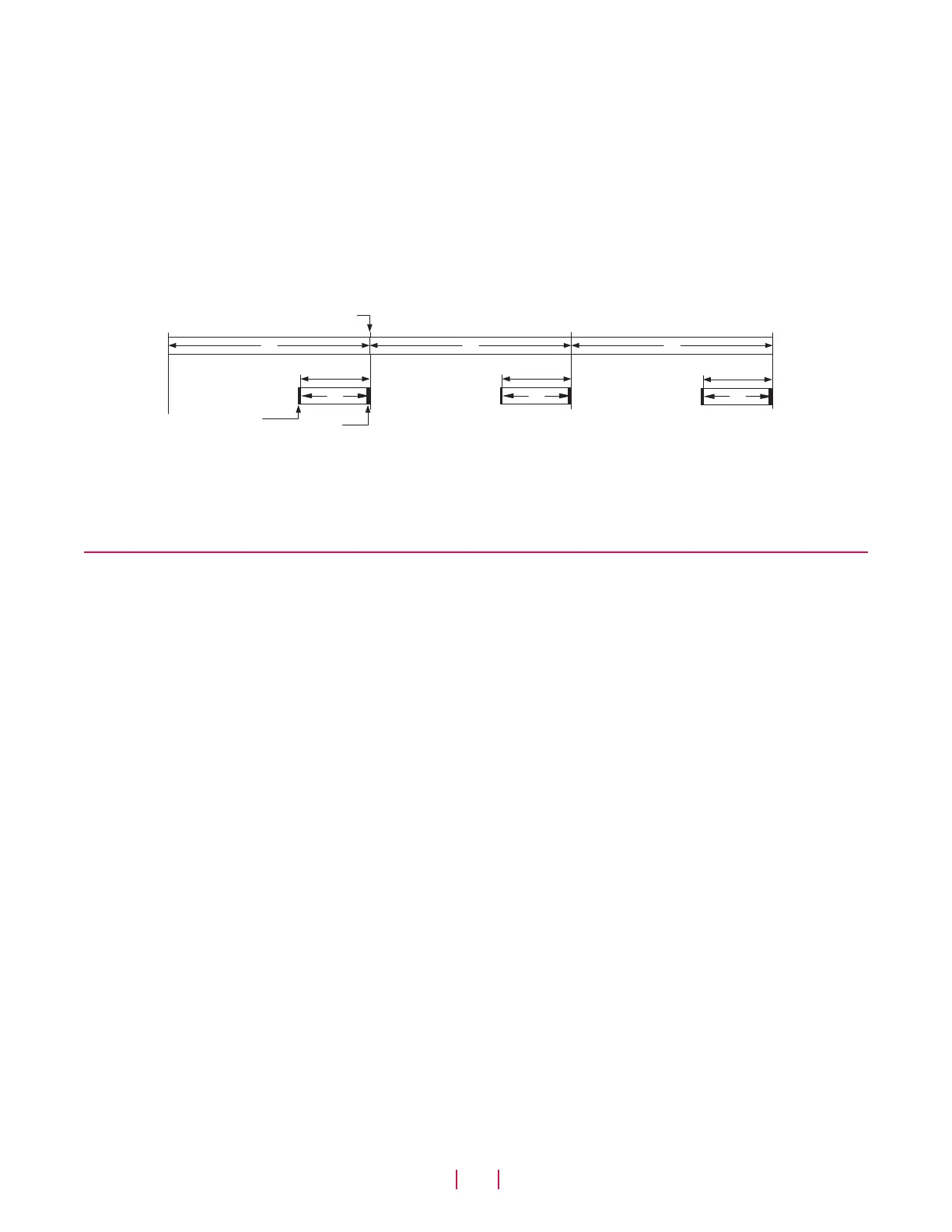
First, the sensor quickly determines the controller’s loop timing – typically after one stable cycle period. Once this is known, and determined
to be repeatable to specified limits, the sensor knows exactly when data will be required. The sensor then determines when to start the next
measurement cycle, delaying the interrogation pulse, so that the measurement cycle will complete just in time to deliver the freshest data
possible when the controller makes the next request, (see ‘Figure 5’).
Controller
loop timing
Sensor
measurement
cycle timing
Measurement starts
Compensation time
Data delivered
T
c
T
c
T
c
Delay
T
s
Delay
T
s
Delay
T
s
Figure 5. Synchronous measuring mode, Sync 1 option
This form of synchronization to the controller provides the high quality position data needed for complex motion control algorithms and
for multiple axes machines requiring tight coordination. When developing applications that will use the Synchronous Measuring Mode, the
designer must choose a controller or PLC input module that supports this mode.
Advanced output options
The Temposonics SSI sensor has advanced output options that are helpful for maximizing system performance in demanding applications
requiring very high accuracy and speed.
ENHANCEMENTS FOR THE SYNCHRONOUS MEASURING MODE (‘SYNC 2’ & ‘SYNC 3’ OPTIONS)
The 'Sync 2' option provides a high speed update feature. When motion control applications require new position data faster than the sensor’s
measurement cycle time, the high speed update feature provides extrapolated data values, calculated on the fly. A prediction algorithm
generates usable position data for delivery to the controller whenever the sensor has not yet completed the next measurement cycle. These
extrapolated values are used by the controller as normally updated position data, allowing very fast controller loop times that are necessary
for tight control of high speed applications.
The 'Sync 3' option provides an additional enhancement to the high speed update feature of Sync 2. For this mode the prediction algorithm is
used for all of the sensor’s position data to compensate for the inherent lag time due to the sensor’s measurement cycle.
LINEARITY CORRECTION OPTION (LCO)
The Linearity Correction Option (LCO) provides improved sensor output accuracy. For most stroke lengths linearity accuracy is improved
up to a factor of 5 resulting in deviations from actual position of less than +/- 20 microns (0.0008 in.). For stroke lengths over 5000 mm
(197 in.), the linearity accuracy is improved up to a factor of 10. Selecting the sensor style and magnet is important (both must be matched
together). Contact the factory for assistance when designing for the LCO in your application.
ERROR DELAY (SKIP FILTER)
For applications having very high shock and vibration levels that exceed the sensor specification ratings the Error Delay (Skip Filter) can be
used to prevent errors being produced on some types of controllers. During these very high shock events the sensor may fail to capture the
magnet return signal, and if so, will normally output a zero position value. The Error Delay will instead repeat the last good output value. For
long duration shock events the Error Delay will continue to repeat the good output value up to the number of times selected.
NOISE REDUCTION FILTER
Complex systems can have various noise sources sometime significant enough to require filtering. If needed, a Simple Moving Average (SMA)
filter function is available to reduce noise effects. The filter algorithm can be adjusted to include the last 2, 4, or 8 output values in the calculated
average.
 Loading...


