2205Q2JE-HO-S6-N_2020.01.
Chapter 2 Compressor Specifications and Structure
SCV-series Screw Compressor 2.4 Compressor Structure and Mechanism
2-12
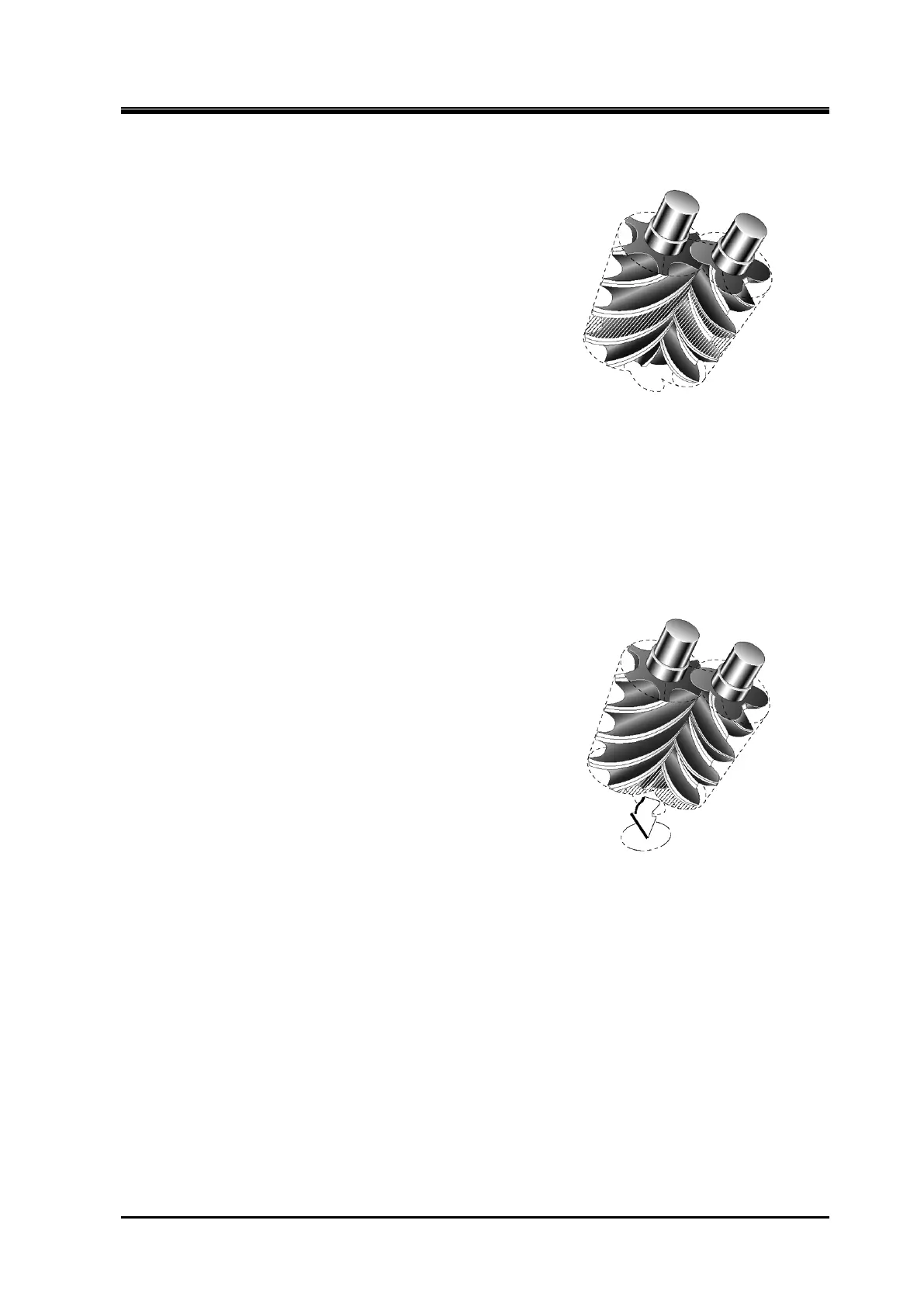
2.4.2.2 Compression Phase
As the rotors rotate further, the volume between the rotor
lobes and grooves decreases while the sealing line moves
toward the discharge side, which compresses the trapped
refrigerant gas.
Figure 2-
7 Compression Phase
2.4.2.3 Discharge Phase
The volume between the rotor lobes and grooves decreases to a level predetermined by the discharge
port. With the rotations of the rotors, the compressed refrigerant gas is pushed out to the discharge
port.
Figure 2-8 Discharge Phase
 Loading...