2205Q2JE-HO-S6-N_2020.01.
Chapter 5 Maintenance and Inspection
SCV-series Screw Compressor 5.5 Reassembly
5-36
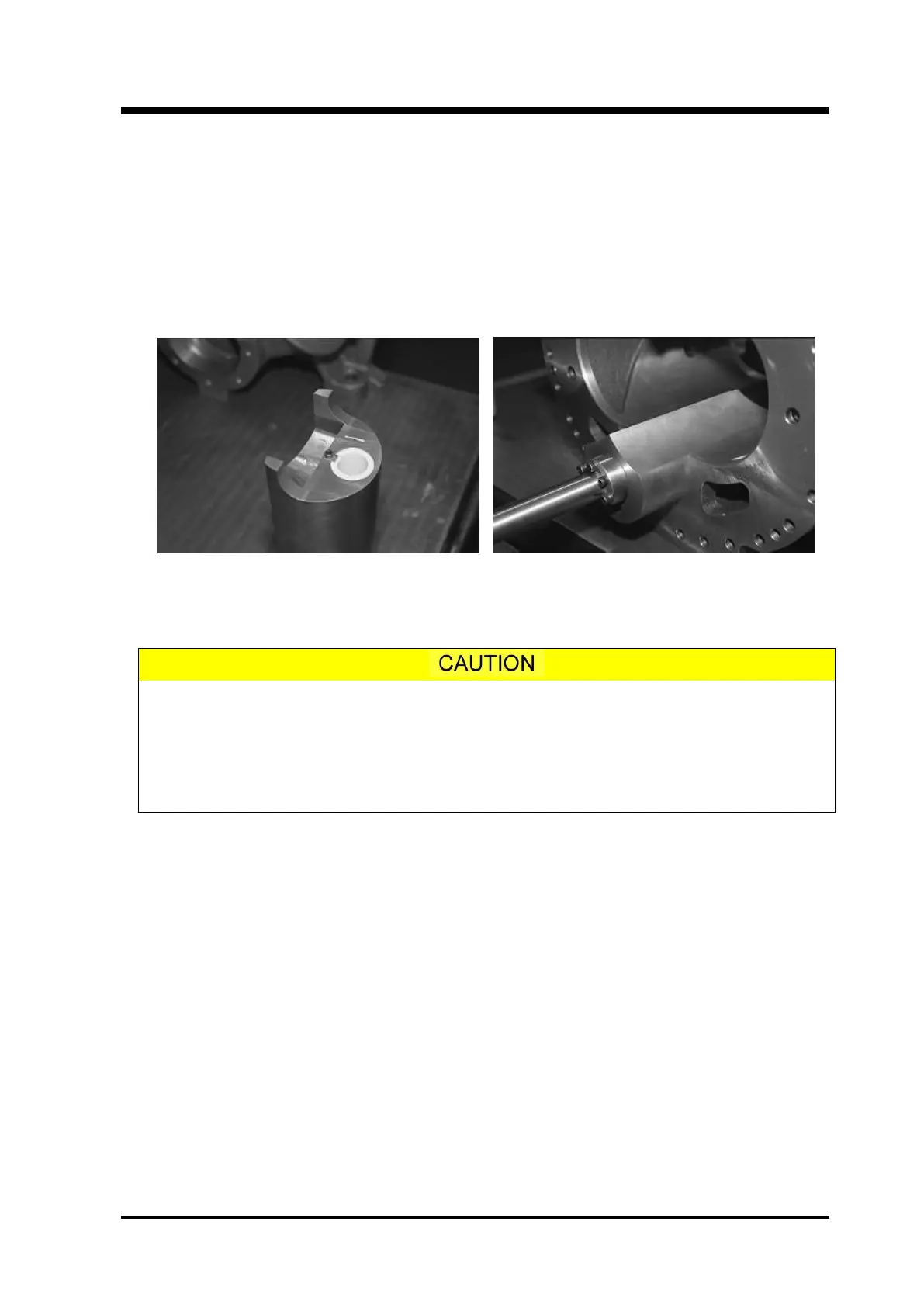
5.5.2 Unloader Slide Valve
a) Check that the O-ring [523] fitted in the Vi adjusting rod hole of the unloader slide valve has replaced,
and check that the Teflon bushing [448] for the Vi adjusting rod has no defects.
b)
Check that all removed plugs for oil injection circuit, etc. of the main rotor casing are fitted into the
original holes.
c)
Install the unloader slide valve to the main rotor casing and confirm that the unloader slide valve
moves smoothly.
d)
Install the variable Vi auxiliary slide valve and confirm that is moves smoothly.
Teflon Bushing Install the Unloader Slide Valve
e)
Apply sufficient oil or like to both sides of the bearing head gasket [12] and attach it to the main rotor
casing. Screw in the stud bolts to the main rotor casing to hold the gasket.
As the bearing head gasket [12] is not symmetrically shaped, carefully check the
orientation when attaching the gasket.
If you place the bearing head gasket by just hanging it on the stud bolts, the gasket
will protrude into the inside of the rotor casing when the casing is assembled. Apply
sufficient amount of oil, etc. to the gasket to make it fully attached to the surface to
prevent protruding upon the assembly.
f) Combine the flange surfaces of the main rotor casing and the bearing head.
g) After lightly fastening two bolts, drive in the alignment pins [3] to fix the position by using a copper or
an aluminum hammer.
h) Tighten the hexagon socket head cap screws in a diagonal sequence, a little at a time, and finally
tighten them to the specified torque using a torque wrench. The bottom bolts that cannot be
fastened on the workbench are to be fastened later on.
i) After tightening the bolts, check that the gasket is not protruding into the inside of the casing. If any
part of the gasket is extending into the bores, there is a possibility that the performance of the
compressor is deteriorated.
j) Also check that the unloader slide valve and variable Vi auxiliary slide valve can be moved smoothly
along the surface of the port section in the bearing head.
k)
Install the Vi adjusting rod from the bearing head side, and screw in it to the screw thread of the
variable auxiliary slide valve. Do not forget attaching the thrust washer.
 Loading...