Chapter 1 GPIB Hardware
© National Instruments 1-7 GPIB Hardware Guide
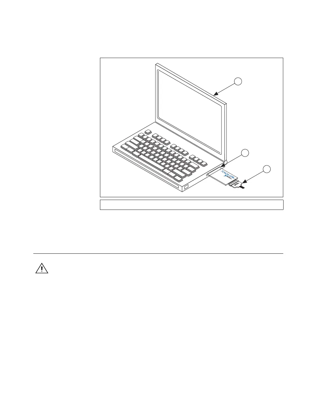
Figure 1-4 shows how to insert the PCMCIA-GPIB and how to connect the
cable.
Figure 1-4. Inserting the PCMCIA-GPIB
The GPIB hardware installation is now complete.
NI ExpressCard-GPIB
Caution The NI ExpressCard-GPIB hardware does not have isolation built into it. If you
have a system where there are different ground potentials involved, the voltage difference
could surge through the GPIB hardware and cause damage. This situation most often
occurs when the PC is a laptop running on a battery and the GPIB device is powered by an
AC wall connection. To prevent damage to the NI ExpressCard-GPIB hardware or other
components in your system when different ground potentials are involved, do any of the
following:
• Buy a GPIB-120A, which can provide up to 1600 V electrical isolation between GPIB
systems. These are available at
ni.com.
• Buy a pair of GPIB-140A units, which extend a GPIB system using fiber optics.
Because the GPIB signals at each end are transformed into fiber optic signals, each
unit can reside at a different ground potential. These are also available at
ni.com.
1 Portable Computer 2 PCMCIA Socket 3 PCMCIA-GPIB Cable
 Loading...