NI myRIO-1950 User Guide and Specifications | © National Instruments | 5
Connector Pinouts
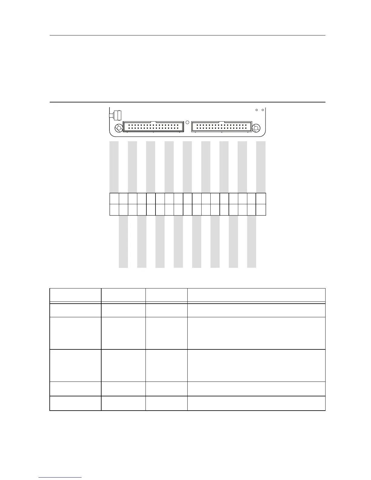
NI myRIO-1950 Expansion Port (MXP) connectors A and B carry identical sets of signals. The
signals are distinguished in software by the connector name, as in
ConnectorA/DIO1 and
ConnectorB/DIO1. Refer to the software documentation for information about configuring
and using signals. The following figure and table show the signals on MXP connectors A and B.
Note that some pins carry secondary functions as well as primary functions.
Figure 3. Primary/Secondary Signals on MXP Connectors A and B
Table 1. Descriptions of Signals on MXP Connectors A and B
Signal Name Reference Direction Description
+5V DGND Output +5 V power output.
AI <0..3> AGND Input 0-5 V, referenced, single-ended analog input
channels. Refer to the Analog Input
Channels section for more information.
AO <0..1> AGND Output 0-5 V referenced, single-ended analog
output. Refer to the Analog Output Channels
section for more information.
AGND N/A N/A Reference for analog input and output.
+3.3V DGND Output +3.3 V power output.
AO0
AO1
AGND
DGND
UART.RX
DGND
UART.TX
DGND
DIO11 / ENC.A
DGND
DIO12 / ENC.B
DGND
DIO13
DGND
DGND
DIO14 / I2C.SCL
DIO15 / I2C.SDA
+5V
AI1
AI3
AI2
DIO1
DIO2
DIO3
DIO4
AI0
DIO0
DIO5 / SPI.CLK
DIO6 / SPI.MISO
DIO7 / SPI.MOSI
DIO8 / PWM0
DIO9 / PWM1
DIO10 / PWM2
+3.3 V
34
33
32
31
30
29
28
27
26
25
24
23
22
21
20
19
18
17
16
15
14
13
12
11
10
9
8
7
6
5
4
3
2
1
 Loading...


