26 | ni.com | NI 9751 User Manual
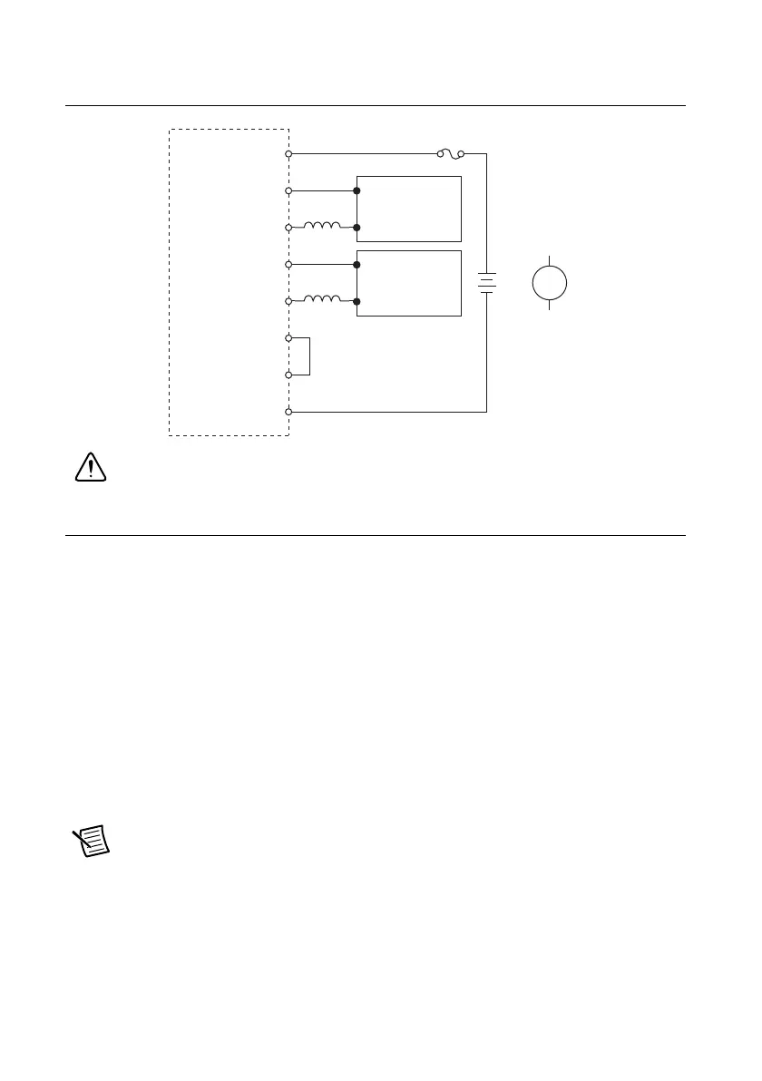
Figure 33 illustrates connecting piezoelectric injectors to your NI 9751.
Figure 33. Connecting Piezoelectric Injectors to the NI 9751
Caution Fuse in Figure 33 is user-supplied and required in all instances.
Specifications
Module Characteristics
Number of channels
Solenoid injectors .....................................3
Standard piezo injectors............................2
Inverted piezo injectors.............................1
Main battery (BATT) input range .....................7 VDC to 32 VDC
Recommended main battery input
power capacity ..................................................≥100 W
External Power (EXT PWR) for
boost power supply replacement.......................24 VDC to 190 VDC
Note When using an external high voltage power supply connected to the EXT
PWR terminal, do not connect this high voltage supply to the BATT terminal.
Connect the BATT terminal to a separate supply of 7 V to 32 V. Connect the ground
of the external high voltage supply to the GND terminal 8.
NI 9751
INJ3–
INJ2+
INJ2–
INJ1+
INJ1–
BATT
INJ3+
GND
Piezo
Injector
Piezo
Injector
or
UL Listed 20 A
Automotive Fuse
12 V to 24 V
Ty pi cal,
150 W
+
+
+
–
–
–
+
–

 Loading...