6. Calculate the current through the shunt by completing the following steps.
a) Take a voltage measurement across the shunt using DMM2.
b) Divide the voltage measurement by the calibrated value of the shunt.
7. Record the current from the previous step as I1.
8. Change the load from Load1 to Load2. Repeat the previous four steps. This time, record
the values as V2 and I2.
9. Calculate the upper and lower current load regulation test limits using the following
formula, and then record the test limits.
Current Load Regulation Test Limit = (V1 - V22) × 0.00025 A/V
10. Calculate the current change using the following formula:
I1 - I2
11. Verify the current change falls within the current load regulation test limits.
12. If more than one level range is specified, repeat the previous steps using the values
specified in each level range.
Remote Sense
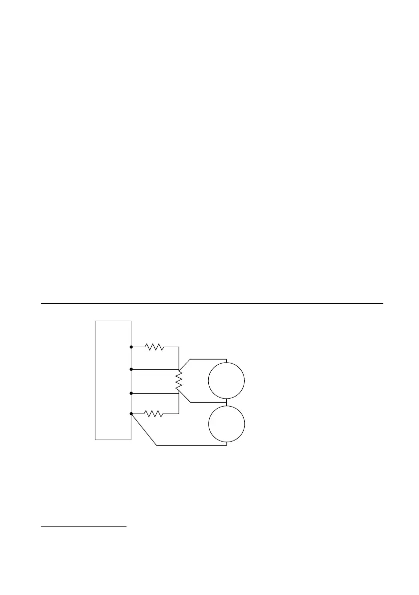
Connecting and Configuring Equipment for Voltage Remote
Sense Accuracy Verification
1. Make the necessary connections for this procedure, as shown in the following figure.
Figure 6. Voltage Remote Sense Output Connection Diagram
6
NI-DCPower Device
Sense –
Sense +
+
–
Load3
Load 2
Load1
DMM2
Voltage
Mode
+
–
DMM
Load Voltage Measurements
DMM
LO Lead Drop Measurements
DMM1
Voltage
Mode
+
–
2. Set the niDCPower Sense property or NIDCPOWER_ATTR_SENSE attribute to Remote.
3. Set the niDCPower Output Function property or NIDCPOWER_OUTPUT_FUNCTION
attribute to DC Voltage for the NI 4113.
6
If you make measurements using only one DMM, sequentially set up the DMM connections as
specified by the procedure steps.
12 | ni.com | NI PXIe-4113 Calibration Procedure
 Loading...