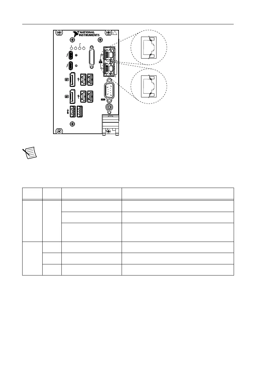
Figure 6. Ethernet Connector Location and Pinout
1
8
1
8
Port 0: Intel I219
Port 1: Intel I210
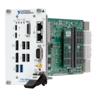
PXIe-8861
Embedded Controller
TRIG
RESET
GPIB
DRIVE
PWR OK/
FAULT
USER1
USER2
ACT/
LINK
Pulse
10/100
/1000
1.2
Note The Ethernet controller can perform an automatic crossover, thus eliminating
the need for crossover cables.
The following table lists and describes the 10/100/1000 LAN connector LED states.
Table 1. 10/100/1000 LAN Connector LED States
LED Color LED State Condition
Top Green Off LAN link is not established.
On (steady state) LAN link is established.
On (brighter and pulsing) The controller is communicating with another
computer on the LAN.
Bottom Unlit Off 10 Mbit/sec data rate is selected.
Green On 100 Mbit/sec data rate is selected.
Amber On 1000 Mbit/sec data rate is selected.
Universal Serial Bus
The following figure shows the Universal Serial Bus (USB) connector locations on the
PXIe-8861. Each controller has four USB 2.0 ports and two USB 3.0 ports on the front panel.
PXIe-8861 User Manual | © National Instruments | 19
 Loading...