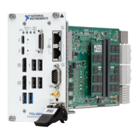
Peripheral External Connector Description
Ethernet Port 1 LAN (RJ45) 10/100/1000 Ethernet connection
Intel I210
USB 2.0 USB 4-pin Series A stacked
receptacle (4 ports)
Hi-Speed USB 2.0
USB 3.2 Gen 1 USB 9-pin Series A stacked
receptacle (2 ports)
SuperSpeed USB, backwards
compatible with USB 2.0
PXI trigger Trigger (SMB) Routing PXI triggers to or from the
backplane trigger bus
GPIB GPIB (25-pin Micro D) General-Purpose Interface Bus, IEEE
488.2
Front Panel Features
The PXIe-8881 has four front panel LEDs that show PC status:
• DRIVE LED— Indicates when an access to the internal drive is occurring.
• PWR OK/FAULT LED—Indicates the controller status. The LED indicates one of the
following states:
– Green ON steady—PXI and onboard power is on and within regulation limits.
– Green BLINKING—The controller has entered the soft off state and is safe to
power down.
Note This status is applicable only when the chassis is set to Manual
Inhibit Mode.
– Green FADING—The controller has entered the standby (S3) state.
– OFF—The controller is powered off.
– Red BLINKING—The controller detected a power rail fault when trying to boot.
– Red SOLID—The controller detected a thermal fault and has shut down to protect
the system.
• USER LEDs — Two bi-color green/yellow LEDs (USER1 and USER2) that you can
define to meet the needs of your LabVIEW application.
Removing the PXIe-8881 from a PXI Express Chassis
To remove the PXIe-8881 from a PXI Express chassis, complete the following steps.
1. Power off the chassis.
2. Remove any cables that may be attached to the controller front panel.
3. Unscrew the four bracket-retaining screws in the front panel.
4. Press the injector/ejector handle down.
6 | ni.com | PXIe-8881 Getting Started Guide

 Loading...