4 | ni.com | RMX Programmable Power Supplies Safety Information & Installation Guide
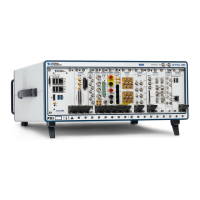
Figure 1. Switchboard Diagram
Connection Procedure
1. Check that the AC power line meets the nominal input rating of the product. The product
can receive a nominal line voltage in the range of 100 VAC to 240 VAC at 50 Hz or 60 Hz.
2. Check that the POWER switch is turned off.
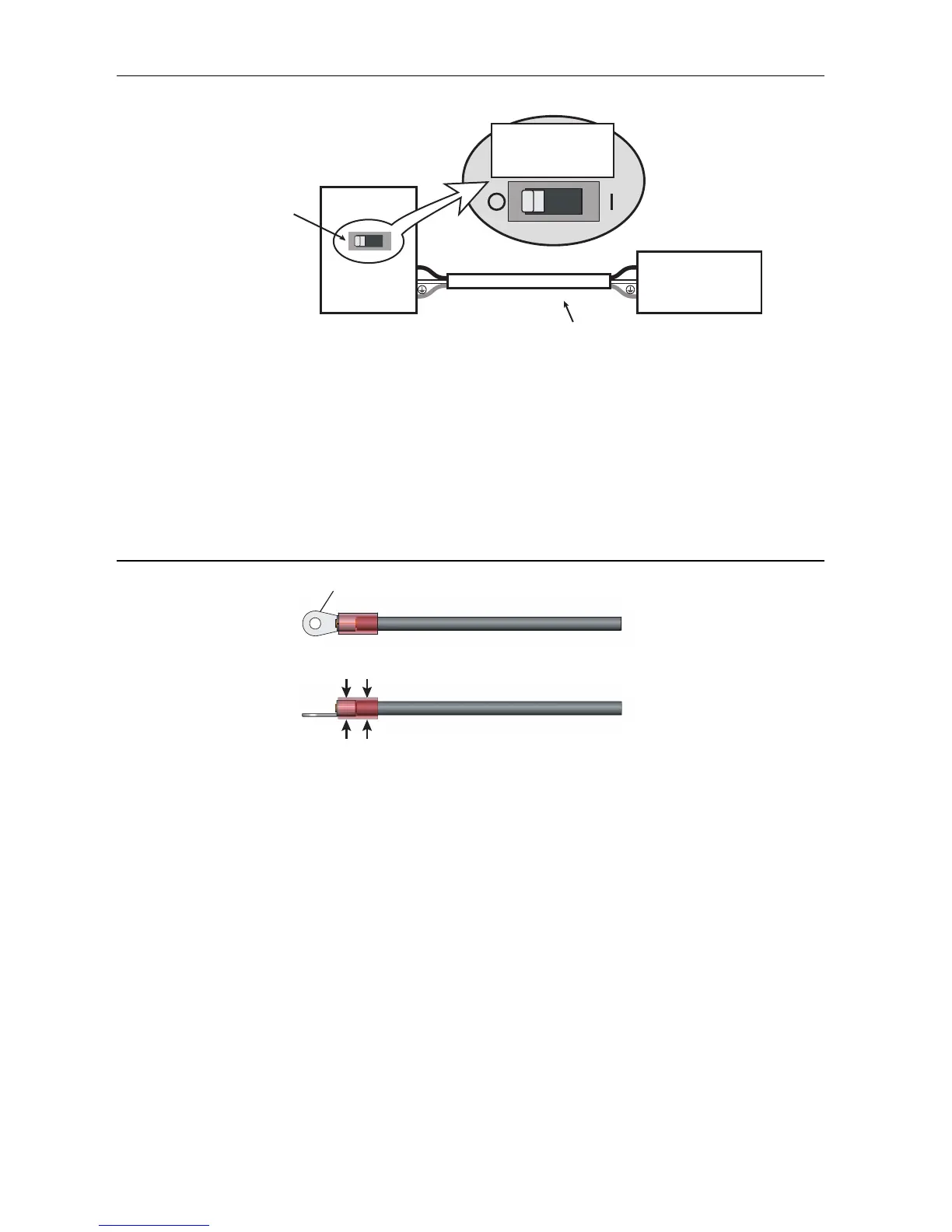
3. Attach a crimping terminal to the GND wire.
Figure 2. Attaching the Crimping Terminal
4. Connect the power cord and the included INPUT terminal cover to the AC INPUT terminal
on the rear panel. Be sure to connect the AC INPUT L, N, and (GND) terminals correctly.
Pass the power cord through the INPUT terminal cover, and fix the cord in place using the
cable gland.
RMX-4125
Switchboard
N
L
N
L
Breaker indication example
For the
RMX-4125 only
30 A
Power cord
RMX-4125
dedicated breaker
Crimping terminal (round, M4)
When crimping the core wire, use a
crimping terminal and tool that can
also grip the insulation.
 Loading...