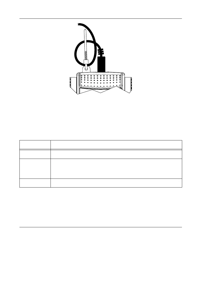
Figure 4. USB Cable Strain Relief
LED Indicator
The green LED next to the USB connector on the NI USB-6501 device indicates device status,
as listed in the following table. When the device is connected to a USB port, the LED blinks
steadily to indicate that the device is initialized and is receiving power from the connection.
Table 1. LED State/Device Status
LED State Device Status
Not lit Device is not connected or is in suspend mode
On, not blinking Device is connected but not initialized, or the computer is in standby
mode. In order for the device to be recognized, it must be connected to a
computer that has NI-DAQmx or NI-DAQmx Base installed.
Single-blink Device is operating normally
Screw Terminal Connector Plugs
The NI USB-6501 ships with two detachable screw terminal connector plugs for digital
signals. These screw terminal connectors accept 16 AWG to 28 AWG wire.
Device Pinout and Signal Descriptions
The following figure shows the digital terminal assignments.
6 | ni.com | NI USB-6501 User Guide

 Loading...


