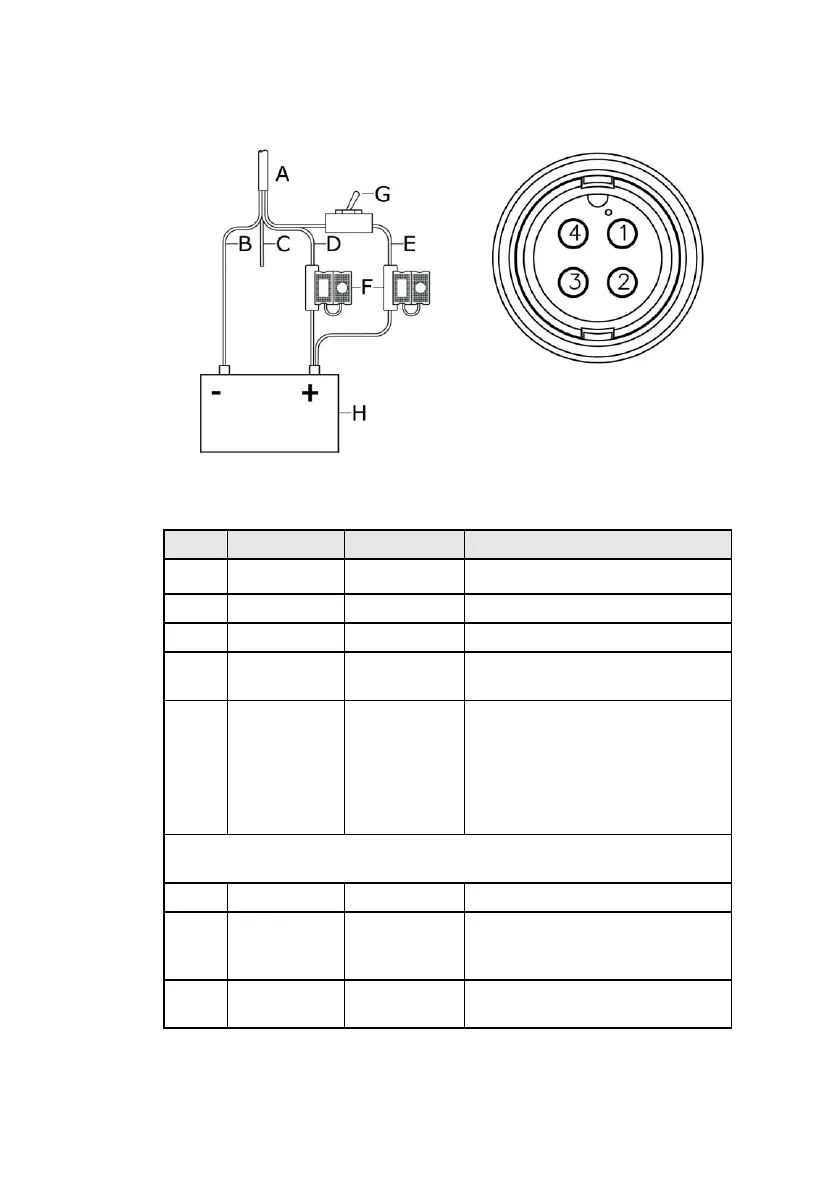
EasyManuals Logo
Home>Navico>Control Unit>BSM-1

Navico BSM-1 User Manual

Navico BSM-1
26 pages
To Next Page IconTo Next Page
To Previous Page IconTo Previous Page
Page #17 background imageLoading...
Page #17 background image
Connecting BSM-1 | 15
EN
Connect power
Power cable connections
Key
Item
Pin
Description
A
Power cable
2 m (6.5 ft) (032-0167-02)
B
BLACK
Pin 1
Connect to DC supply negative.
C
BLUE
Pin 2
No connect.
D
RED
Pin 4
Connect to DC supply positive
12-24 V DC use supplied fuse
E
YELLOW
Pin 3+4
* Ignition sense. Connect to
DC supply positive 12-24 V DC
via a on/off switch (pin 3).
** Connect to DC positive in
common with RED. Use
supplied fuse
NOTE:
GB-40 and 8000i Power cable ignition sense wire is gray,
NSE Displays Power cable ignition wire is yellow
F
Fuses
3 A
G
Switch
Connect via a switch at console
(not included) to turn off BSM-
1 when not in use.
H
Battery
12 or 24 V DC (Max range 9-32
V DC)
* BSM-1 connected GB40 or 8000i network via an Ethernet
Linker.

Questions and Answers:

Question and Answer IconNeed help?

Do you have a question about the Navico BSM-1 and is the answer not in the manual?

Navico BSM-1 Specifications

General IconGeneral
BrandNavico
ModelBSM-1
CategoryControl Unit
LanguageEnglish