77Installing a Common Vent System
9.2 Navien Backflow Damper (Back-draft
Damper)
The Navien backflow damper prevents backflow (back-draft) at the
exhaust vent while the boiler unit operates.
By closing the exhaust vent as soon as the combustion cycle ends,
the Navien backflow damper retains heat in the system for longer
periods. This improves the system’s thermal efficiency.
Note
When using a common vent in a cascade system,
backflow devices are required to prevent exhaust
from entering the building.
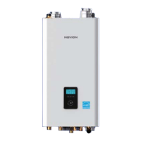
Included Items
Backflow Damper
Installation Manual
Con
d
ens
i
ng
W
a
t
er
H
e
ate
r
Common Vent System
Installation Manual
Fo
r NPE Se
ries Wa
t
er Heat
e
rs
Ce
rti
e
d
to
AN
S
I
Z
2
1
.
1
0
.3
–
C
S
A
4.
3.
(On
l
y
f
or
U
.S
.
in
st
a
ll
a
t
i
o
n
s
)
K
e
e
p
t
h
i
s
ma
n
ua
l
f
o
r
fu
t
u
r
e
r
e
fe
re
n
ce
wh
e
n
e
ve
r
m
a
i
n
te
n
a
n
c
e
o
r
s
er
v
ic
e
i
s
r
e
q
u
i
re
d
.
-
Do
n
ot
s
t
ore
or
us
e
g
a
s
ol
i
n
e
o
r
o
the
r
am
m
ab
le
v
a
p
o
r
s
a
n
d
l
iq
uid
s
in
t
h
e
v
i
c
i
ni
ty
of
t
h
i
s
o
r a
n
y
ot
h
e
r
a
p
p
l
i
a
n
c
e
.
-
WH
AT
T
O
DO
I
F
Y
OU
S
ME
L
L
G
A
S
●
D
o
n
o
t
tr
y
to
l
i
gh
t
a
n
y
ap
pl
i
a
n
c
e
.
●
D
o
n
o
t
to
u
c
h
a
n
y
e
lec
tr
i
c
al
sw
i
t
ch
;
do
n
ot
u
s
e
a
n
y
ph
o
n
e
i
n
y
o
u
r
b
u
i
l
d
i
ng
.
●
I
m
me
d
iat
e
l
y
ca
l
l
yo
u
r
gas
s
up
pl
i
e
r
fr
o
m
a
n
e
ig
h
b
o
r’
s
ph
o
n
e
.
F
o
ll
o
w
th
e g
a
s
s
u
ppl
i
e
r
’
s
i
n
s
t
r
u
c
t
i
o
ns
.
●
I
f
y
o
u
c
an
n
o
t
r
e
ac
h
y
o
u
r
g
a
s
s
u
ppli
e
r
,
c
a
ll
th
e
r
e
d
e
p
a
rtme
n
t
.
-
In
st
a
ll
a
t
i
o
n
a
n
d
s
er
v
ice
m
us
t
b
e
pe
rf
o
r
me
d
by
a
qu
a
l
i
e
d
in
s
t
a
l
l
e
r
,
ser
v
i
ce
a
g
e
n
cy
o
r t
h
e
g
a
s
s
u
p
p
l
ie
r
.
-
T
hi
s
e
n
t
ire
m
a
n
ua
l
m
us
t
b
e
le
f
t
f
or
t
h
e
c
o
n
su
me
r.
T
h
e
con
su
m
er
m
u
st
r
e
a
d
a
n
d
r
e
f
er
t
o
t
h
i
s
ma
nu
a
l
f
o
r
pr
o
p
er
o
p
er
at
i
o
n
a
n
d
m
a
int
en
an
c
e
of
t
h
e
c
o
m
m
o
n
v
e
n
t
sy
s
te
m.
-
T
he
i
ns
t
a
l
l
a
t
io
n
m
u
s
t
c
onfo
rm
w
i
t
h
l
o
c
al
co
d
e
s
or
,
in
th
e
ab
s
en
c
e
o
f
lo
cal
c
od
es
,
th
e
N
a
ti
ona
l Fue
l
G
a
s
Co
d
e
,
AN
SI
Z
2
2
3
.
1
/
NF
PA
5
4.
-
W
h
e
n appl
ic
able
,
t
he
in
st
a
lla
ti
on
m
us
t
c
o
n
f
orm
w
ith
t
h
e
Ma
n
u
f
a
c
t
u
r
ed
Ho
me Co
n
st
r
u
ct
i
o
n
a
nd
S
a
f
et
y
St
a
nd
a
r
d
,
T
i
t
l
e
2
4
C
FR
,
Pa
r
t
32
80,
M
ob
i
le
Ho
m
e
s.
WARNI
N
G
I
f
t
h
e i
n
f
o
r
mat
i
o
n
i
n
th
e
s
e in
s
tr
u
c
t
i
on
s
is
n
ot
f
o
ll
o
we
d
e
xa
c
tl
y
,
a
r
e
or
explo
s
i
o
n
ma
y
r
es
u
l
t
,
c
a
u
s
i
n
g
p
r
o
p
e
r
t
y
d
a
m
a
g
e
, pe
rs
o
n
a
l
i
n
j
u
r
y
,
o
r
d
e
a
th
.
Co
n
dens
in
g
W
ater
H
e
at
er
Common Ven
t
System
Installati
on Manual
Fo
r
N
PE Series
W
ater Heat
e
rs
C
e
r
ti
e
d
t
o
AN
SI
Z
2
1
.
10.
3
–
C
S
A
4.
3.
(
On
l
y fo
r
U.
S
.
i
n
st
a
l
l
a
ti
on
s)
Ke
e
p
th
is
man
ua
l
fo
r
f
ut
ur
e
r
ef
e
re
nce
wh
e
n
e
v
er
ma
i
n
t
e
n
a
n
c
e
or
serv
i
c
e
i
s
r
e
q
ui
re
d.
-
Do
n
ot
s
to
re
or
u
s
e
g
a
so
l
i
n
e
or
oth
er
amm
a
b
le
v
a
p
or
s
an
d
l
iq
ui
d
s
in
th
e
v
i
c
i
ni
t
y
of
t
hi
s
o
r
a
n
y o
th
e
r
ap
pl
i
a
n
c
e
.
-
WH
A
T
T
O
D
O
IF
Y
O
U
S
M
E
LL
GAS
●
Do
n
ot
tr
y
to
li
gh
t
a
n
y
ap
pl
ianc
e
.
●
Do
n
ot
to
u
c
h
a
n
y
e
lec
t
r
i
c
a
l
sw
it
c
h
;
d
o
n
o
t
u
s
e
a
n
y
p
h
o
n
e
i
n
y
o
u
r
bu
i
ldi
n
g
.
●
I
mmed
i
a
t
e
ly
ca
ll
yo
u
r
ga
s
s
u
p
p
l
i
e
r
fr
o
m
a
n
ei
g
h
b
o
r’
s
p
h
o
n
e
.
F
o
ll
o
w
th
e
g
a
s
s
u
pp
l
ie
r
’
s
i
n
s
t
r
u
c
t
i
on
s
.
●
If
y
o
u
ca
n
n
o
t
re
ac
h
y
ou
r
g
a
s
s
up
p
li
er
,
c
all
t
he
r
e
de
pa
rtm
e
n
t
.
-
I
n
sta
l
la
t
i
o
n
a
n
d
s
er
v
i
c
e
m
us
t
be
p
erf
o
rm
ed
b
y
a
q
u
a
l
i
e
d
i
ns
t
a
l
l
e
r,
ser
vic
e
age
n
c
y
o
r
t
he
ga
s
s
u
p
p
l
i
e
r
.
-
T
h
i
s
e
n
t
ire
m
a
n
u
a
l
m
us
t
b
e
l
e
f
t
f
or
th
e
c
o
n
su
m
e
r
.
The
co
n
s
um
e
r
m
u
st
r
e
a
d
a
n
d
r
e
f
e
r
t
o
t
h
i
s
m
a
n
u
a
l
f
o
r
p
ro
p
e
r
op
er
at
io
n
an
d
m
a
i
nt
e
n
a
n
c
e
of
t
h
e
c
om
m
on
v
e
nt
s
ys
t
em
.
-
T
h
e
i
n
s
t
a
l
l
a
t
i
o
n
m
u
s
t
c
o
n
f
or
m
w
i
t
h
l
oc
al
c
o
d
e
s
or,
in
th
e
ab
s
en
c
e
of
l
o
ca
l c
o
d
e
s
,
t
h
e
N
a
t
i
o
na
l
Fue
l
G
a
s
C
o
d
e
,
A
N
SI
Z
2
2
3
.1/
NF
P
A
5
4
.
-
Wh
e
n
ap
p
l
i
c
ab
l
e
,
t
h
e
i
ns
t
al
l
at
i
o
n
mus
t
c
o
n
f
o
r
m
w
i
t
h
t
h
e
M
a
nu
f
a
ct
u
r
ed
H
om
e
C
o
n
s
t
ru
c
t
io
n
an
d
Sa
f
e
t
y
St
an
d
a
rd
, Ti
t
l
e
2
4
C
FR
,
Pa
r
t
32
80
,
M
ob
i
le
Ho
m
e
s.
WA
RNI
NG
I
f
t
h
e
i
n
f
o
r
m
at
i
o
n
i
n
t
h
e
s
e
i
n
s
t
r
u
ct
i
o
n
s
is
n
ot
fo
l
lo
w
e
d
ex
a
c
t
ly
,
a
r
e
o
r
explo
s
i
on
ma
y
r
es
u
lt
,
cau
s
i
n
g
pr
o
p
e
rt
y
d
am
a
g
e
, pe
rson
a
l
i
n
j
u
r
y
,
o
r
d
e
a
t
h
.
Ready-Link
communication
cable
Screw (4 ea)
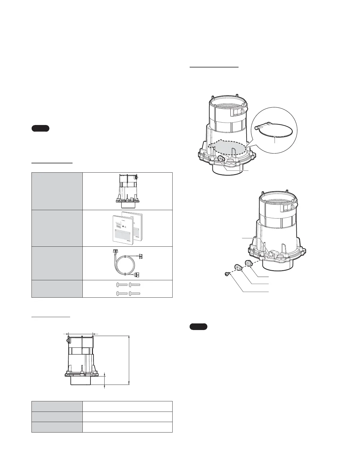
Specifications
8.1” (206 mm)
3” (76 mm)
1.6” (42 mm)
Part Name Backflow Damper
Part No. 30022799A
Material PP (Polypropylene)
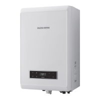
Maintenance Port
Navien Backflow Damper has a maintenance port to allow you to
easily inspect the operating condition of the damper plate.
Maintenance port
Damper plate
Maintenance port
Gasket
Maintenance port cover
Fix screw
Refer to “9.9 Maintenance” for detailed inspection procedures.
Navien Backflow Damper (Back-draft Damper)
Note
When using a common vent in a cascade system,
backflow devices are required to prevent exhaust
from entering the building.
 Loading...