63Setting the DIP Switches
CAUTION
Do not remove the front cover unless the power to the
boiler is turned off or disconnected. Failure to do so may
result in electric shock.
The boiler has 2 sets of DIP switches on the main circuit board
(PCB). DIP switches are used to control the functionality of the
boiler. Set the DIP switches appropriately, based on the installation
environment.
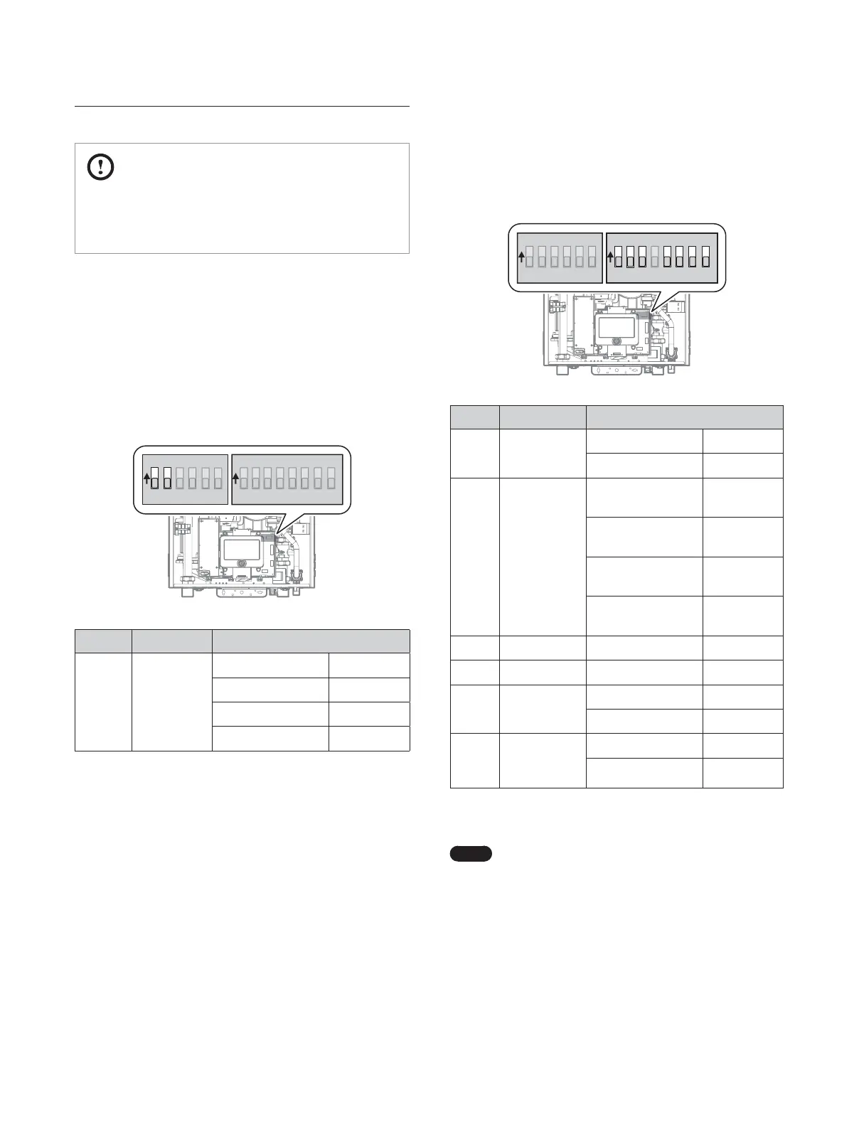
6.1 DIP Switch 1 (6 switch unit)
The DIP SW 1 on the circuit board configures the operation status
and model/capacity settings.
1 2 3 4 5 6
O
N
O
N
1 2 3 4 5 6 7 8
Switch Function Setting
1 & 2
Operation
Status
Normal Operation 1-OFF, 2-OFF
2Step MAX 1-ON, 2-OFF
1Step MIN 1-OFF, 2-ON
1Step MAX 1-ON, 2-ON
6.2 DIP Switch 2 (8 switch unit)
The DIP SW 2 on the circuit board configures the gas type, country,
and enables or disables the space heating thermostat.
1 2 3 4 5 6
O
N
O
N
1 2 3 4 5 6 7 8
Switch Function Setting
1 Gas Type
Natural Gas 1-OFF
Propane Gas 1-ON
2 & 3 High Altitude*
0-1,999 ft
(0-609 m)
2-OFF, 3-OFF
2,000-5,399 ft
(610-1,645 m)
2-ON, 3-OFF
5,400-7,699 ft
(1,646-2,346 m)
2-OFF, 3-ON
7,700-10,100 ft
(2,347-3,078 m)
2-ON, 3-ON
4 Reserved - -
5 & 6 Country US/Canada 5-OFF, 6-OFF
7
Space Heating
Thermostat
Used 7-OFF
Unused 7-ON
8
Exhaust
Temperature
Control
Used 8-OFF
Unused 8-ON
* For high altitude installations, the gas orifice plate must be replaced with
the proper orifice for use above 5,400 ft. Refer to “12.1 Gas & High Altitude
Conversion” for details.
Note
When PCB DIP switch 2 #8 is set to On, ensure that
CPVC, approved polypropylene, or stainless steel is
used for exhaust venting.
6. Setting the DIP Switches
 Loading...