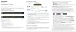
Installation
NETGEAR 48-Port Gigabit PoE+ Smart Managed
Pro Switch With 4 SFP Ports
Switch Model GS752TPv2 or GS752TPP
Package Contents
• NETGEAR Gigabit PoE+ Smart Managed Pro Switch
• AC power cord (localized to country of sale)
• Rubber footpads for tabletop installation
• 19-inch rack-mount kit for rack installation
• Resource CD
Configure the Switch With a Static IP Address
If your network uses a DHCP server, this section does not apply. Go
directly to Connect the Switch to a Network.
If you are using static IP addresses in your network, configure the switch IP
address before you connect the switch to a network.
1. Configure a computer with a static IP address in the 192.168.0.x subnet.
2. Plug the switch into a power outlet and connect your computer to the switch
using an Ethernet cable.
3. Open a web browser and enter 192.168.0.239 in the address bar.
The default IP address of the switch is 192.168.0.239.
A login page displays.
4. Enter password for the password.
The System Information page displays.
5. Select System > Management > IP Configuration.
The IP Configuration page displays.
6. Select the Static IP Address radio button.
7. Enter the static IP address, subnet mask, and default gateway IP address that
you want to assign to the switch.
8. Click the Apply button.
Your settings are saved.
Connect the Switch to a Network
1. Connect devices to the RJ-45 PoE network ports on the switch front panel.
Use Category 5e (Cat 5e) Ethernet cables terminated with RJ-45 connectors
to make Gigabit connections.
2. Connect an RJ-45 port or SFP port on the switch to a network that includes a
DHCP server.
Note: In a small oce or home oce network, connect the switch to the LAN
port of a router that, in turn, is connected to an Internet modem.
If you use an SFP port, you must insert an SFP transceiver module, which is
available from NETGEAR.
3. Power on the switch and wait two minutes.
Check the PoE Status
The switch can supply up to 30W PoE+ (IEEE 802.3at) to each port. The
maximum PoE power budget across all active PoE+ ports is 380W for the
GS752TPv2 switch and 760W for the GS752TPP switch.
The PoE Max LED indicates the status of the PoE budget on the switch:
• O. Sucient (more than 7W of) PoE power is available.
• Solid yellow. Less than 7W of PoE power is available.
• Blinking yellow. At least once during the previous two minutes, less than 7W
of PoE power was available.
Configure the Switch
You can use a web browser or the NETGEAR Smart Control Center Utility (see
Smart Control Center Utility) on your Windows-based computer. If you are
unsure how to determine the IP address of the switch, use the Smart Control
Center Utility.
Make sure that you are running the latest firmware version on your device.
To find documentation, firmware, soware, or other files, visit
downloadcenter.netgear.com.
Web Browser Access
1. Open a web browser on a computer that is on the same network and subnet
as the switch and enter the switch’s IP address.
A login page displays.
2. Enter password for the password.
The System Information page displays.
3. Configure the switch for your network.
For information about switch configuration, see the user manual for your
switch, which you can download from downloadcenter.netgear.com.
Sample connection
PoE access points
PoE VoIP phone
Switch
Network
Internet