6 www.neutonpower.com
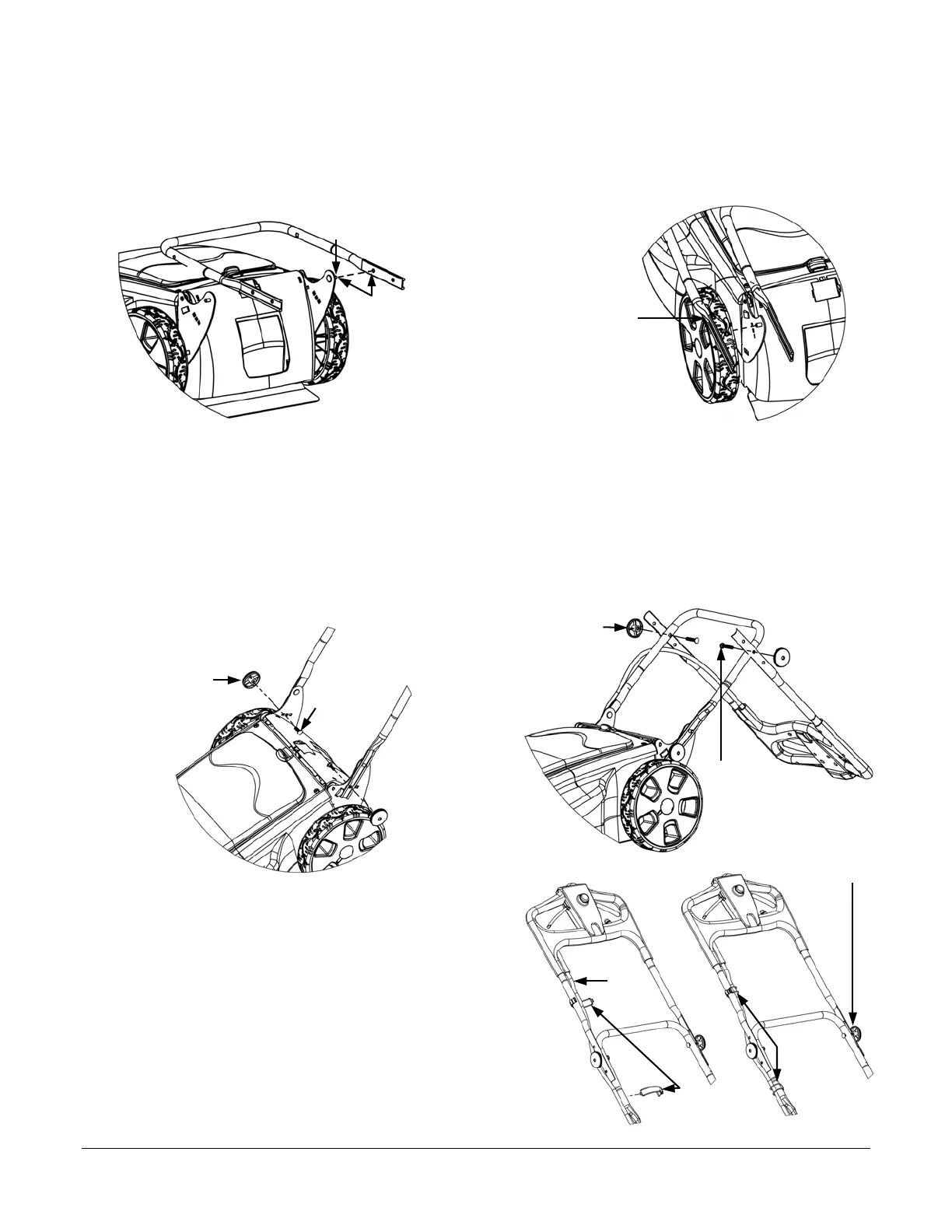
Step 3: Attach and Adjust the Lower and Upper Handlebars.
1. Lay the Lower Handlebar on top of the Mower and align the hole shown in Figure 3 with the Stud on the Right Handlebar
Bracket. Once you align the holes, slide the Handlebar to the left to engage the hole with the Stud.
2. Lift and pull the Left Side of the Lower Handlebar over the Left Handlebar Bracket (Figure 4), and align the hole in the
Handlebar with the Stud as shown. Once you align the hole with the Stud, gently allow the Lower Handlebar to spring
back into place, whereby the Stud will protrude through the hole.
NOTE: Be sure to hold the Lower Handlebar in a location where your hand(s) are not prone to pinching between the Lower
Handlebar and the Handlebar Bracket.
3. Rotate the Handlebar into the upright position (Figure 5) and insert the two (2) 8mm x 25mm Carriage Bolts (the smaller of
the four (4) Bolts included with your Neuton Product Pack) from the inside through one of the three (3) holes and screw on
the Black Handlebar Connector Knobs also included in the Neuton Product Pack. Tighten the Connector Knobs by hand.
NOTE: The three (3) holes in the Handlebar Brackets through which you can pass the 8mm x 25mm Bolts are Height
Adjustment Holes. The lowest hole will produce the highest Handlebar position and the highest hole will produce the
lowest position for operation.
4. Let the plastic portion of the Upper Handlebar Assembly lean on the ground (Figure 6) and align one of the three (3) holes
in the Upper Handlebar Assembly with the hole on the Lower Handlebar. Insert the larger, 8mm x 45mm Carriage Bolt
from the inside through the aligned holes and lightly screw on the remaining Black Connector Knobs, just enough to hold
the Upper and Lower Handlebar Sections together.
5. Rotate the Upper Handlebar Assembly to the upright position
so that the Upper and Lower Handlebars align and tighten the
Handlebar Connector Knobs by hand until snug (Figure 7).
6. Position the Main Cable along the Handlebars and secure it
in place by holding the two (2) Main Cable Retainers in
place while stretching the rubber strap around the Cable,
and securing it into the Hook on the Retainer (Figure 7).
Figure 3 Figure 4
Hole
aligned
with Stud
Carriage Bol
(shorter)
Figure 5
Main
Cable
Retainers
Handlebar
Connector Knob
Mounting Bracket Stud
Handlebar
shown moved
to the outside
of the Bracket.
Figure 6
Carriage Bol
(longer)
Handlebar
Connector Knob
Figure
Main
Cable
Cable
Retainers
in
lace
Handlebar
Connector Knob(s)
 Loading...