Installer manual
Component positions
Till PBD
Till MOS
D
E
*
min 200
F
A
Till KBR
C
B
54
40
min ???
Till PBD
Till MOS
D
E
*
min 200
F
A
Till KBR
C
B
54
40
min ???
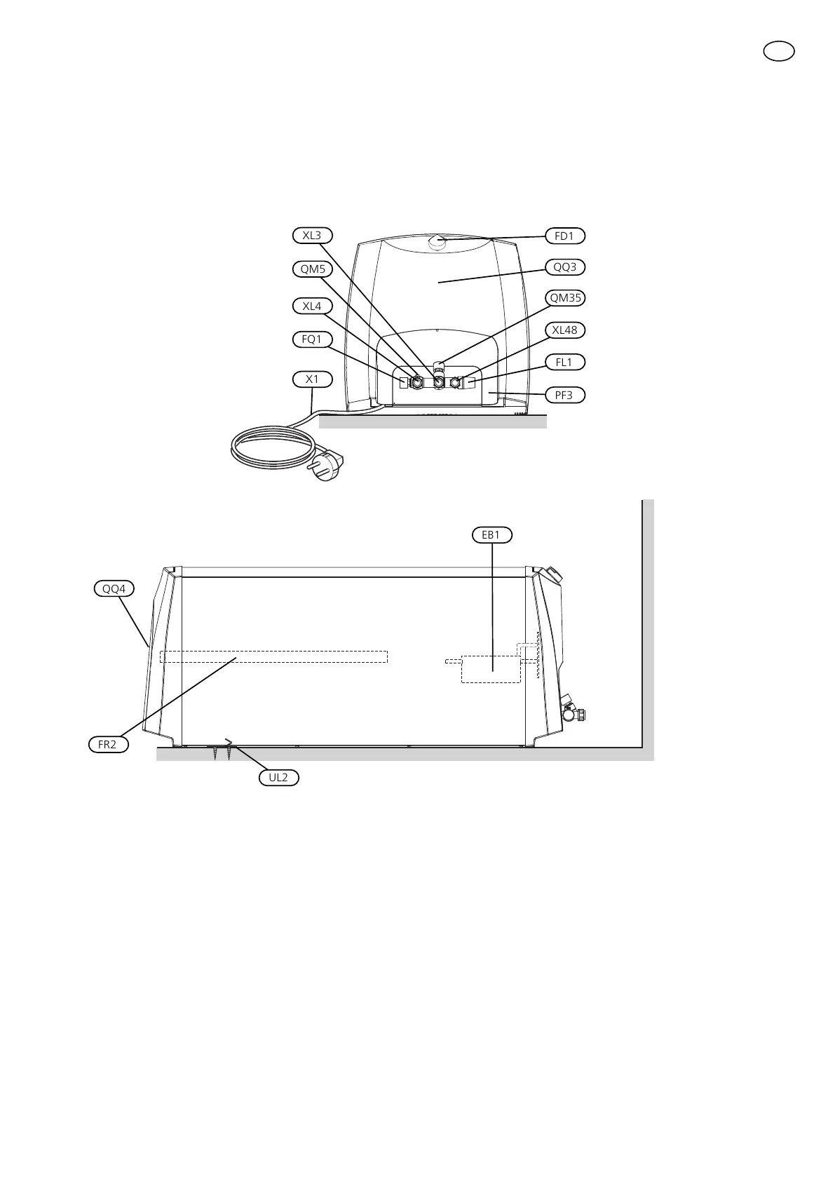
XL3
EB1
FR2
QQ4
UL2
QM5
XL4
FQ1
X1
PF3
FL1
XL48
QM35
QQ3
FD1
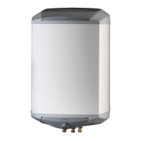
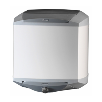
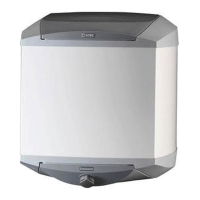
List of components
FL1 Safety/drainage valveX1 Power cable with earthed plug, length 850 mm
FQ1 Mixer valveQQ3 Plastic cover, junction box
FR2 Sacrificial anode (EMINENT- E)QQ4 Plastic cover, anode (EMINENT-E)
XL3 Cold water connection, compression ring coupling Ø15
mm
FD1 Thermostat/temperature limiter
XL4 Hot water connection, compression ring coupling Ø15
mm
EB1 Immersion heater
XL48 Connection safety/draining valve, compression ring
coupling Ø15 mm
UL2 Hanging bracket
QM5 Vent screw (for air supply during draining)UL3 Securing bracket
PF3 Serial number plateQM35 Shutoff/non-return valve
23Eminent
 Loading...