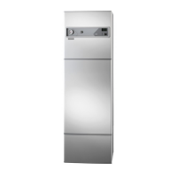
13VEDEX 3300
For the Installer
Electrical installation
Electrical installation
If the connection cable is damaged or
becomes otherwise unusable, it must be
replaced by the manufacturer, its service
agent or other qualified person to prevent
any danger.
NOTE!
Connection
VEDEX 3300 must be installed via an isolator switch with
a minimum breaking gap of 3 mm or be supplied with a
suitable plug connector.
The boiler must be connected under the supervision of an
authorised electrician. The connection cable for electrical
connection is on the reverse of the boiler. There is a con-
nection area for electrical connection behind the front
panel (33).
The charge pump is powered from the electrical socket on
the reverse of the boiler, max. total current output is 10 A.
Min cable area 1.5 mm
2
.
Switch (45) set in position ”0” means that the boiler is off.
Position ”1” is the normal operating position.
With thermal valve
The thermostat is supplied connected for charge control
with a thermal valve (laddomat 21 or similar).Connection
of the return line from the accumulator tanks is to the re-
turn connection (84) on the boiler.
The flue gas thermostat (2) starts and stops the flue gas
fan. When the green light comes on, the flue gas thermo-
stat’s set temperature has been reached and the flue gas
fan starts. Max thermostat (3) stops the flue gas fan when
the boiler temperature exceeds the set value. This is to re-
strict combustion and prevents the boiler temperature from
getting too high. The charge thermostat (19) stops the ex-
ternal charge pump when the boiler temperature exceeds
the set value. The automatic charge control ensures that
the risk of condensing does not occur and manages the
transfer of heat from the boiler to the accumulator tanks.

 Loading...