10
EN
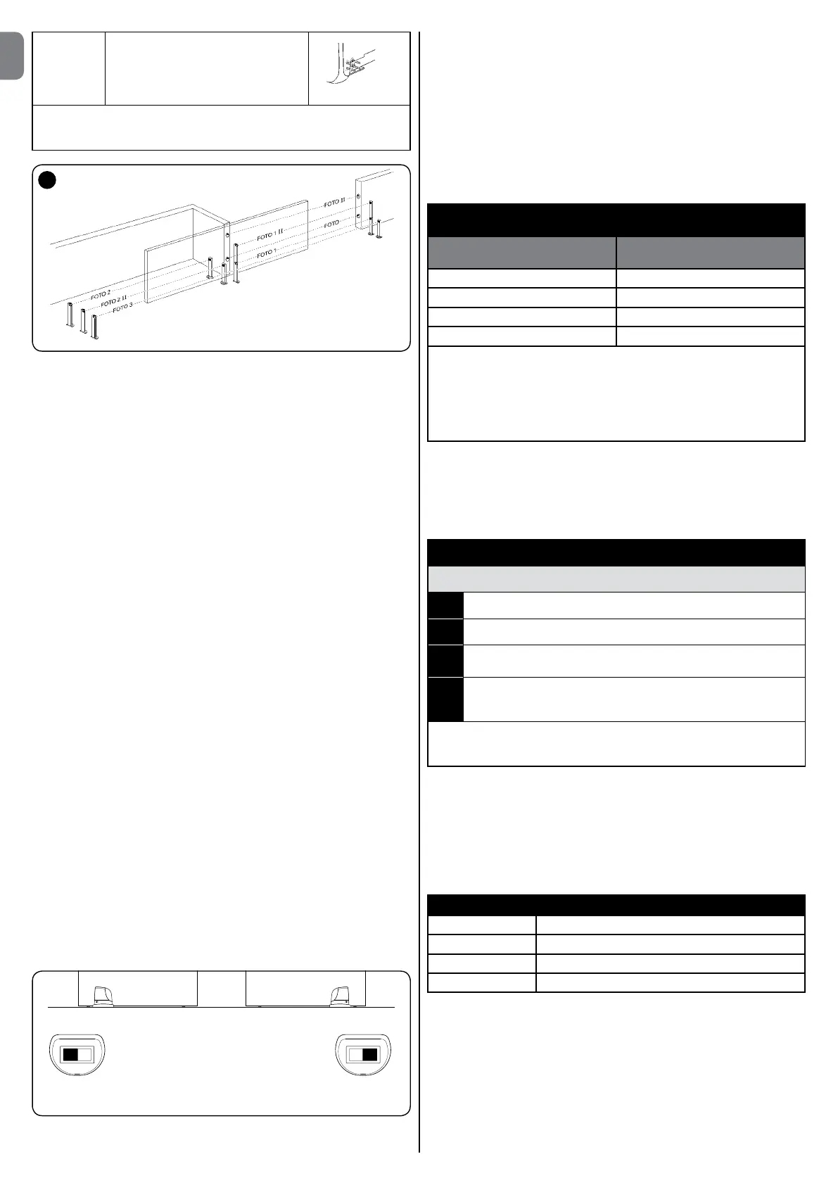
FOTO 3 Single photocell for the entire
automation system
IMPORTANT– in the case of the installation of FOTO 3 and FOTO II
together the position of the photocell elements (TX-RX) must comply with
the provisions contained in the photocell instruction manual.
A
8.1.4 - FT210B Photo-sensor
The FT210B photo-sensor unites in a single device a force limiting device (type
C in accordance with the EN1245 standard) and a presence detector which
detects the presence of obstacles on an optical axis between the TX transmit-
ter and the RX receiver (type D in accordance with the EN12453 standard). The
sensitive edge status signals on the FT210B photosensor are transmitted by
means of the photocell beam, integrating the two systems in a single device.
The transmitting part is positioned on the mobile gate and is powered by a bat-
tery thereby eliminating unsightly connection systems; the consumption of the
battery is reduced by special circuits guaranteeing a duration of up to 15 years
(see the estimation details in the product instructions).
By combining a FT210B device to a sensitive edge (TCB65 for example) the
level of security of the “main edge”, required by the EN12453 standard for all
“types of use” and “types of activation”, can be attained.
Photosensor FT210B combined with “resistive” sensitive edges (8.2 kOhm), is
safe with single faults (class 3 per EN 954-1). It is equipped with a special anti-
collision circuit to prevent interference with other detectors, even not synchro-
nised, and enables the addition of other photocells; for example in the case of
transit of heavy vehicles where a second photocell is normally positioned at 1
m from the ground.
See the FT210B instructions manual for further information concerning con-
nection and addressing methods.
8.1.5 - RUN“Slave”mode
Properly programmed and connected, RUN can function in “Slave” mode; this
type of function is used when 2 opposite gates need to be automated with
the synchronised movement of the two gates. In this mode one RUN works
as Master commanding the movement, while the second RUN acts as Slave,
following the commands transmitted by the Master (all RUNs are factory set to
operate as Masters).
To configure RUN as a Slave, level one “Slave mode” must be activated (see
table 6).
The connection between RUN Master and Slave is made via BlueBus.
ATTENTION– In this case the polarity of the connections between the
twoRUNsmustberespectedasillustrateding.18(theotherdevices
remain with no polarity).
Follow the operations below to install 2 RUNs in Master and Slave mode:
• Installthe2motorsasindicatedintheFigure.Itisnotimportantwhichmotor
is to function as Slave or Master; when choosing, one must consider the
convenience of the connections and the fact that the Step-by-Step com-
mand of the Slave only allows the Slave gate to be opened fully.
• Connectthe2motorsasshowning.18.
• Selecttheopeningdirectionofthe2motorsasshowninthegure(seealso
paragraph 5.1 Choosing the direction).
• Supplypowertothe2motors.
• Program“SlaveMode”ontheSlave RUN (see Table 6).
• RundevicerecognitionontheSlaveRUN(seeparagraph8.1.6Recognition
of the devices).
• RundevicerecognitionontheMasterRUN(seeparagraph8.1.6Recognition
of the devices).
• RungatelengthrecognitionontheMasterRUN(seeparagraph5.4Recogni-
tion length of the gate).
When connecting 2 RUNs in Master-Slave mode, make sure that:
• AlldevicesmustbeconnectedtotheMasterRUN(asinfig.18)includingthe
radio receiver.
• Whenusingbackupbatteries,eachmotormusthaveitsownbattery.
• AllprogrammingoftheSlaveRUNisignored(theMasterRUN'sprogram-
ming overrides the others), except for that mentioned in table 11.
TABLE11-ProgrammingSlaveRUNsindependentlyofthe
Master RUN
Level 1 functions
(ON–OFFfunctions)
Level 2 functions
(adjustableparameters)
Stand-by Motor speed
Peak Open Gate Indicator Output
Slave Mode Motor force
Error list
On Slave it is possible to connect:
• Aasher(Flash)
• Anopengatelight(S.C.A.)
• Asensitiveedge(Stop)
• Acommanddevice(StepbyStep)thatcontrolsthecompleteopeningof
the Slave gate only
• TheOpenandCloseinputsarenotusedontheSlave
8.1.6 - Recognition of Other Devices
Normally the recognition of the devices connected to the BlueBus and the STOP
inputtakesplaceduringtheinstallationstage.However,ifnewdevicesareadded
or old ones removed, the recognition process can be gone through again by pro-
ceeding as shown in Table 12.
TABLE 12
Recognition of Other Devices
01.
Press and hold down “s” and “Set”;
02. Release “Set” when led L1startsashing;
03. Release the keys when the “L1” and “L2”ledsstarttoashquickly
(after around 3s);
04. AttheendoftherecognitiontheL1andL2ledswillstopashing,
the STOP led must stay on, while the L1...L8 leds will come on
based on the status of the ON-OFF functions they represent.
IMPORTANT – After you have added or removed any devices, the automa-
tion system must be tested again according to the directions contained in
paragraph 6.1 “Testing”.
8.1.7 - Radioreceiver
The “SM” radio receiver connector for SMXI or SMXIS type optional radio
receivers has been provided in order to enable the user to control RUN from a
distance.
For further information consult the radio receiver instructions manual. To insert
the radio receiver, follow the operations indicated in Figure 20. In Table 13 there
is a description of the association between the radio receiver output and the
command that RUN will perform:
TABLE13-CommandswithSMXI,SMXISreceivers
Output N°1 Step-by-step (STEP-BY-STEP)
Output N°2 Partial open
Output N°3 Open
Output N°4 Close
8.1.8 - Connecting up the Oview programmer
The unit has a BusT4 connector for connection of the Oview programming unit
permitting complete, rapid management of installation, maintenance and diag-
nosis of the entire automation mechanism. To access the connector, proceed
as shown in Fig. 21 and connect up the connector in the housing provided.
The Oview may be connected to multiple units simultaneously (up to 16 with no
particular precautions, up to 60 with the warnings stated) and may be left con-
nected up to the unit during regular operation of the automation mechanism.
In this case, it may be used to send commands directly to the unit using the
“user” menu. You may also update Firmware. If the unit has a radio receiver in
the OXI/OXIT family, you may use Oview to access the transmitter parameters

 Loading...