MEASUREMENTS
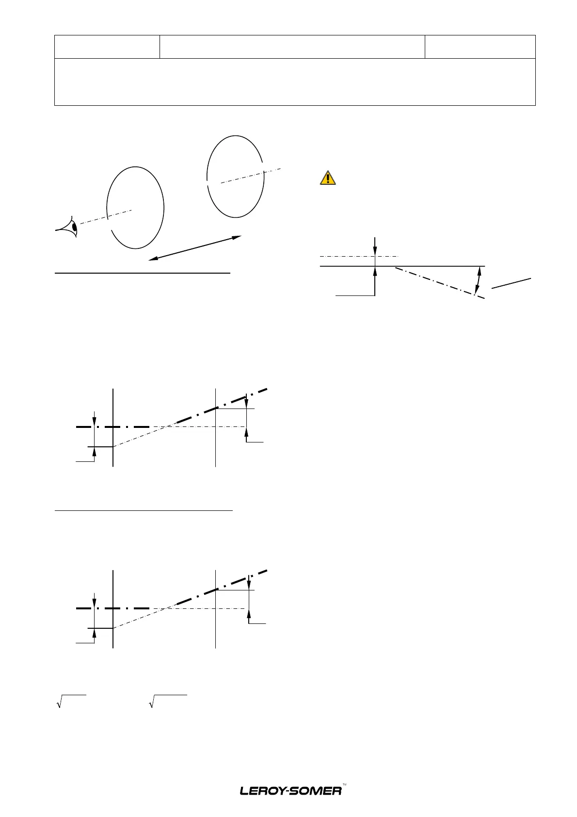
Measurements referring to the vertical plane:
Considering the vertical plane "C1" : The vertical action
towards the top of shaft "A" on the micrometer is dominant.
In the plane "C1" the axis "A" is higher than axis "B”
( 0.9 – 0.1 ) / 2 = - 0.05 mm
In the vertical plane "C2", the vertical action towards the
top of shaft "B" on the micrometer is greater.
In the plane "C2" the axis "B" is higher than axis "A"
( 0.134 – 0.102 ) / 2 = 0.16 mm
The respective position of the axes is as follows:
Regarding the vertical plane the angular alignment error is:
( 0.16 + 0.05 ) *100 / 400 = 0.0525 mm/100mm (not
acceptable)
Measurements referring to the horizontal axis:
In the plane "C1" the axis "B" is further to the right than "A”
( 0.104 – 0.86 ) / 2 = 0.09 mm
In the plane "C2" the axis "B" is further to the left than "A”
( 0.70 - 1.64 ) / 2 = - 0.47 mm
The representation of the shafts is as follows:
Regarding the horizontal plane the angular error is:
( 0.47 + 0.09 ) *100/ 400 = 0.14 mm/100mm (not
acceptable)
In the both planes the parallelism error is:
or
(not
acceptable)
3.3.2 Two bearings machine alignment (flanged)
3.3.2.1 Machines without axial end play (standard)
The alignment must take the tolerances of the coupling into
account.
CAUTION:
A MISALIGNMENT EVEN IF ACCEPTABLE BY THE
COUPLING MUST NOT CREATE STRESSES LEVEL
NOT ACCEPTABLE BY THE BEARING
Shafts alignment limits to follow:
0.08 mm
parallelism error
To check the alignment, there are different methods: the
"double concentricity" method is described in the
"alignment procedure" chapter 3.3.1.6.
Electric Power Generation
Installation and maintenance
5654 en - 2017.10 / a
LSA 52.2 MHV
Industrial Range Alternators - 4 pole
13
 Loading...