- A 0 ・ -
VBA18001-R.3719.A
logo�Q0440�forGraphic
070518�Gdesign�ito
・
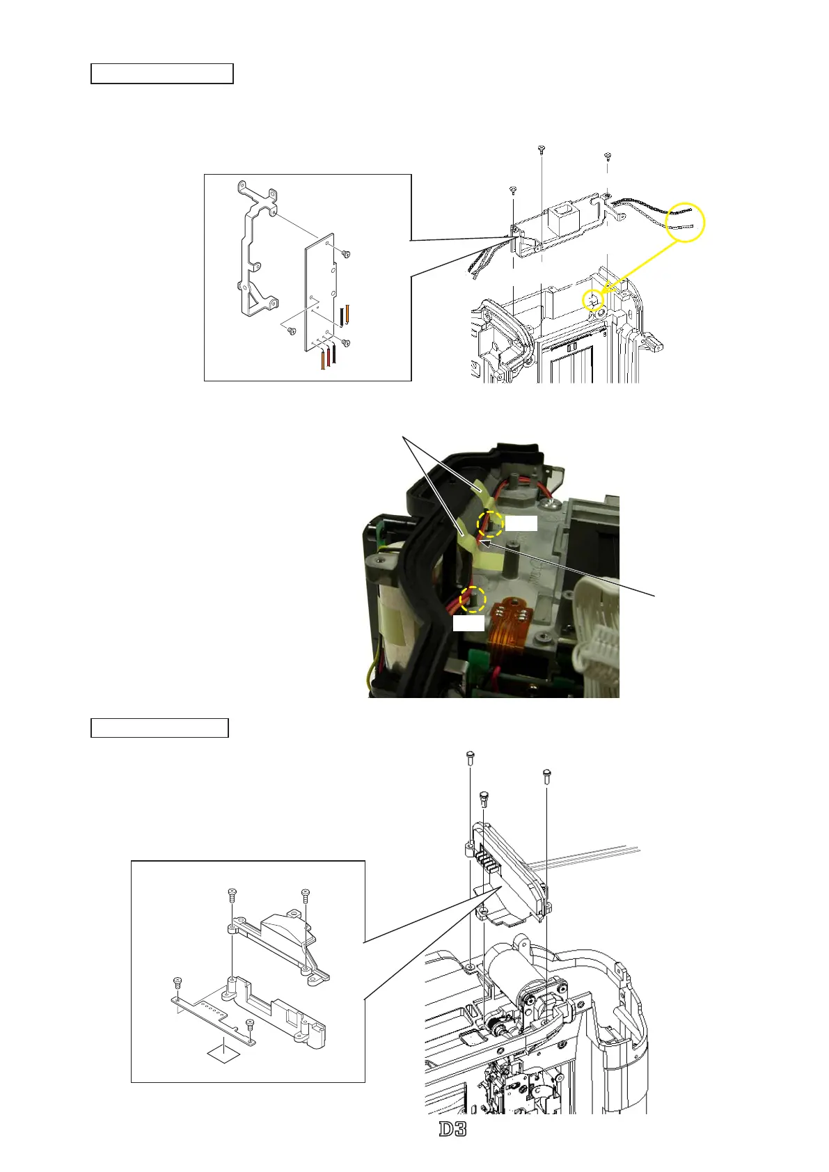
Mount the battery contact base unit section.
・
Tighten two screws (#1538) and one screw (#928).
#1538×2
Battery contact section
#928
#1568×2
#1565×2
TA-0005
#801
#803
#B5053
Battery contact section
Battery contact unit
・
Arrange the wires between the bosses.
・
Attach two pieces of the tape (
TA-0005×2
).
Wire
TA-0005×2 (10×20)
Boss
Boss
・
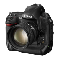
Mount the DC-IN PCB section.
・
Tighten one screw (#1532) and two screws (#1523).
#1532
#1523×2
DC/IN PCB section
DC/IN PCB section
#1530×3
#396
Pass the wire
through the hole.
DC-IN PCB section
DC/IN PCB
#5024