- A ・ -
VBA18001-R.3719.A
logo�Q0440�forGraphic
070518�Gdesign�ito
【
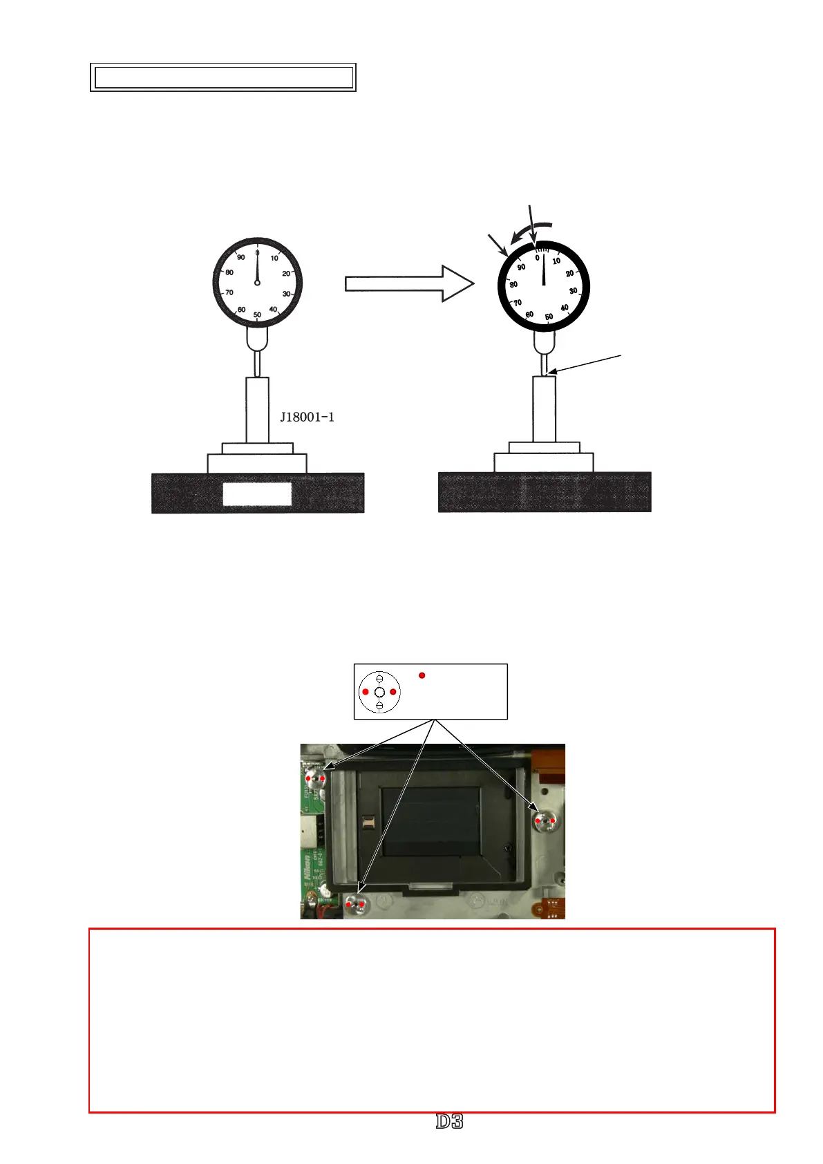
"0" positioning of Dial gauge
】
①
Put the tool (J18001-1) on the surface plate.
②
Turn the index circle in the direction of the arrow by three scale markings.
This is "0" position of D3.
【
How to measure
】
・ Measure six places from the bayonet face to the image PCB attaching face.
Standard: 48.64±0.015mm / Parallelism: 0.015mm or less
・ In case it is out of standard, make an adjustment by putting the washer on the contact surface between the
front body and rear body.
"0" position of D3
①
Index circle
②
Measurement terminal
Note: For some bodies, the washer(s) is/are already put on the attaching face of the image sensor unit.
There is a red mark indication at the following two positions.
1. Indication: on the attaching face of the camera body side
Purpose
:
To adjust the height of the camera body
2. Indication: on the attaching face of the image sensor unit side
Purpose
:
To adjust the height of the image sensor unit
Therefore, in case of the above 1. and when the camera body is disassembled or the image sensor is
replaced, put the washer(s) at the original position. In case of the above 2. and when the image sensor unit
is replaced, remove the washer.(s)
"
" Places to be
measured
0
0
0
0
0
0
0
0
0
0
Inspection and Adjustment of Body back
Surface plate
 Loading...