page 5
MOUNTING
Your power unit mounts to the wall using a mounting system.
The wall mounting bracket, provided with your power unit,
mounts to the wall. It has 4 fingers at the top and 4 more at the
bottom. The power unit has 4 upper openings and 4 lower
openings which are designed to slide onto the wall mounting
bracket fingers. Ensure to follow the instructions below for
proper installation.
1. Locate power unit within six feet (1.82 m) of a grounded
electrical outlet. NuTone VX475CC and VX550CC power
units require a 120 V, dedicated 15-amp branch-circuit with
a NEMA 5-15R receptacle or a dedicated 20-amp branch
circuit with a NEMA 5-20R receptacle. NuTone VX1040CC
power unit requires a 240 VAC, dedicated 20-amp branch
circuit with a NEMA 6-20R receptacle.
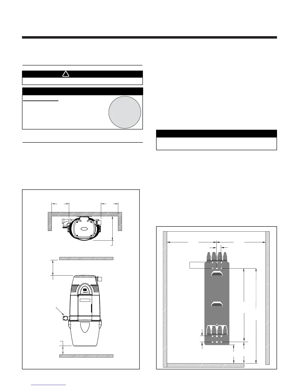
2. Refer to Fig. 2 to maintain minimum wall clearance
dimensions.
3. Position and install the wall mounting bracket with the
provided screws. Refer to Fig. 3 for proper mounting
dimensions.
4. Using the provided mounting screws, secure the mounting
bracket on the wall through two upper and two lower
mounting holes.
5. Hang power unit onto wall mounting bracket. Ensure both
upper and lower mounting openings on the back of the
power unit are engaged with corresponding wall bracket
fingers. Pull the power unit down to secure.
6. Open the door located on the front of the power unit.
Ensure the cyclonic filter is properly seated.
See page 13 for reference. Close the door.
WALL MINIMUM CLEARANCE DIMENSIONS
F
IG. 2
F
IG. 3
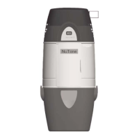
POWER UNIT
INSTALLATION
For all models, DO NOT REMOVE
either of the grey seals covering the
TOP red cap plugs. Removing these
seals will void the warranty. Only
remove and use the outlets covered
by the BOTTOM green plugs.
 Loading...