5
INTRODUCTION
Measurement of power output levels of diagnostic and
therapeutic ultrasound equipment has become increas-
ingly important to determine exact patient exposure lev-
els in case a potential risk exists to the patient. Since the
Radiation Control for Health & Safety Act of 1968 and the
1976 Medical Device Amendments to the FDA Act be-
came effective, all manufacturers of diagnostic Doppler
ultrasound equipment are required to submit information
regarding their maximum peak and average exposure
level, beam patterns, and other pertinent information.
Hospitals are responsible for regularly scheduled testing
(every six months) of output power and safety to main-
tain their accreditation.
The Ultrasound Power Meter, Model UPM-DT series, is
designed to measure the ultrasound power output of di-
agnostic or therapeutic transducers up to 30 watts. The
principle of measurement is the radiant force method.
The UPM-DT-1 and UPM-DT-10 are mechanically identi-
cal, each having a positioning clamp to hold the trans-
ducer in de-gassed water above a conical target. The
ultrasonic energy passes through the water to reflect off
the target and is then absorbed by the rubber lining. The
radiant power is directly proportional to the total down-
ward force (weight) on the target. This weight is then
transferred through the target support assembly to the
electro-mechanical load cell inside the scale. The cell is
in a computer-controlled feedback loop and produces a
digital readout in watts of power (custom units) or grams
of force. The choice of units (grams or watts) is selected
by front panel pushbuttons. The units are supplied with a
plug-in 120 VAC to 24 VAC 50/60Hz adapter. A me-
chanical shock mounting in the carrying case protects
the electronic balance mechanism. Model UPM-DT-1
has a display resolution of ±2 milliwatts and Model UPM-
DT-10 has a display resolution of ±10 milliwatts.
UNPACKING THE UPM-DT POWER METER
The power meter comes complete with all accessories in
a sturdy carrying case. To make ultrasonic measure-
ments, the water tank requires only one pint of de-
gassed water. If de-gassed water is not available, use
distilled water, NOT tap water.
The following replacement parts can be ordered if neces-
sary from Ohmic :
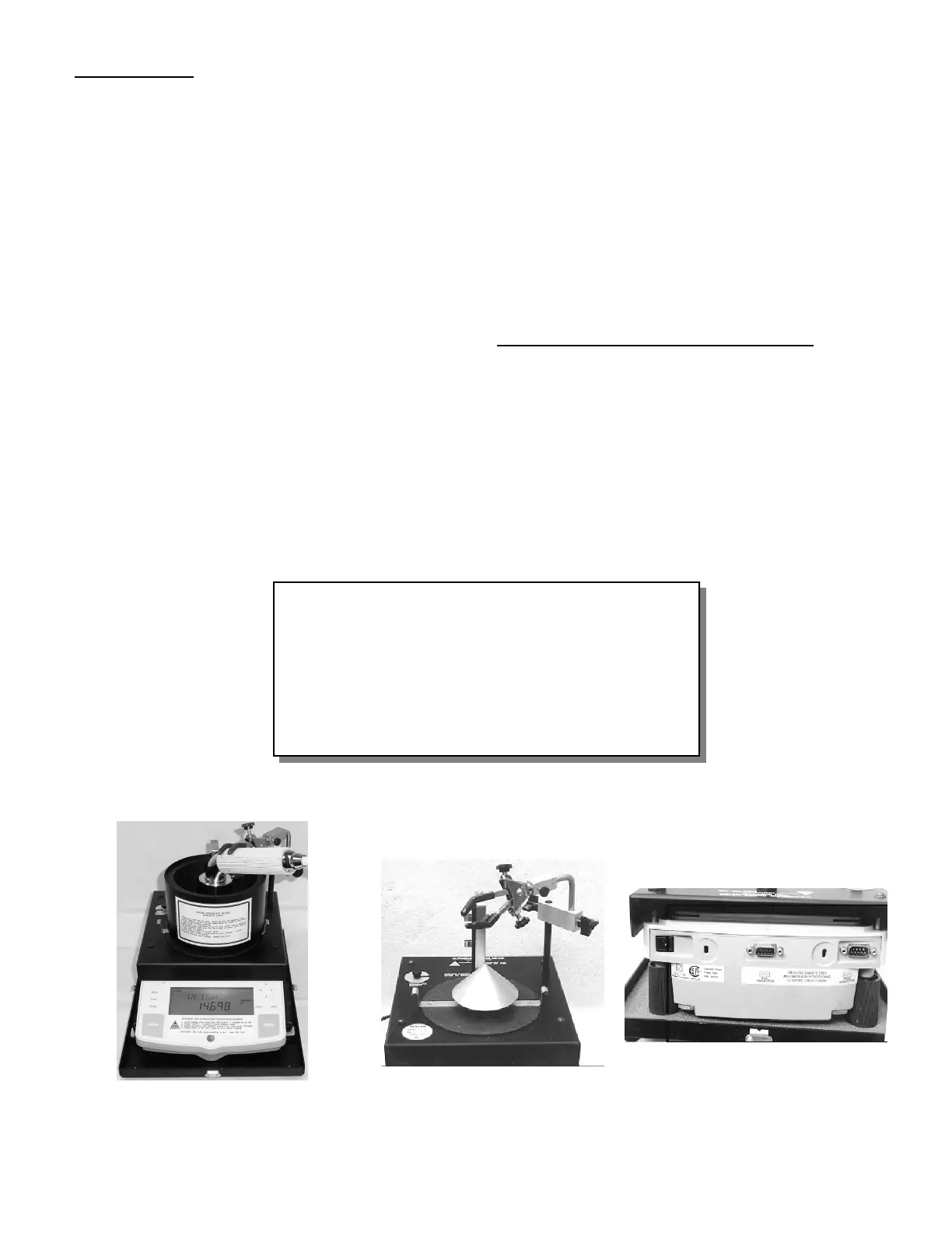
The picture above shows the cone
target assembly and transducer
positioner (Tank not shown).
The rear panel of the UPM-DT Series
provides power and RS-232 computer /
printer connections. Adjustments to level
the unit are made by rotating the rear
stands.
Front view of UPM-DT-1 & 10. Shown is the
electronic balance, base assembly, test tank
& transducer positioner.
Test Tank with Rubber
Positioning Clamp Assembly
Cone Assembly
Calibration Weight Standard [specify Ohmic #53001]
Detachable Line Cord / 120 VAC Adapter
Instruction Manual [specify “DT1-10_MANUAL.PUB”;
available in PDF format]
Carrying Case
 Loading...