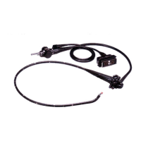
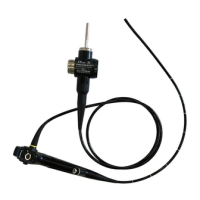
2.1 Nomenclature and functions
19
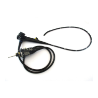
BF-190 Series OPERATION MANUAL
Ch.2
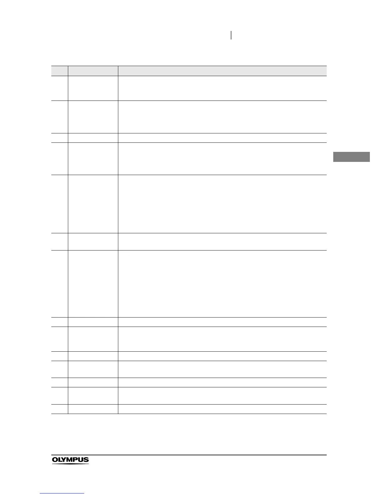
No. Nomenclature Description
1UP/DOWN
angulation control
lever
When this lever is operated in the “U” direction, the bending section moves UP; when
the lever is operated in the “D” direction, the bending section moves DOWN.
2 Single use suction
valve (MAJ-209) or
suction valve
(MAJ-207
*1
)
*1 These products may not be available in some areas.
The suction valve is depressed to activate suction. The valve is also used to remove any
fluid or debris adhering to the objective lens.
3 Control section Operates the endoscope, such as controlling angulation.
4 Single use biopsy
valve (MAJ-210) or
biopsy valve
(MD-495
*1
)
This valve is attached to the instrument channel port, and an EndoTherapy accessory
can be inserted or a syringe can be attached.
5 Instrument channel
inlet
An EndoTherapy accessory can be inserted into this port. The instrument channel inlet
is connected to the instrument channel outlet on the distal end via the instrument
channel.
The instrument channel functions are as follows:
• Channel for the insertion of EndoTherapy accessories
• Suction channel
• Fluid feed channel (from a syringe via the biopsy valve)
6 Instrument channel
port
Attach the biopsy valve to this port.
7 Color code This color code and numeral show the compatibility of EndoTherapy accessories.
• Blue: BF-Q190, BF-H190, BF-P190
• Yellow: BF-1TH190
• White: BF-XP190
The endoscope can be used with EndoTherapy accessories that have the same color
code. For more information on combining the endoscope with particular EndoTherapy
accessories, refer to “Combination equipment” on page 83 and the instruction manuals
for the compatible accessories.
8 Boot Protects the junction between the insertion tube and control section from bending.
9 Insertion section This section is inserted into the patient body cavity. It can be rotated to the left and right
at angles up to 120 respectively on the control section by rotating the insertion tube
rotation ring.
10 Distal end The objective lens and light guide lens are on this distal end.
11 Bending section The bending section moves the distal end of the endoscope when the UP/DOWN
angulation control lever is operated.
12 Insertion tube Connects the control section and bending section.
13 Remote switches 1
to 4
The functions of the remote switches 1 to 4 can be selected on the video system center.
Refer to the instruction manual for the video system center when setting these functions.
14 Suction cylinder Attach the suction valve to this cylinder.
 Loading...