- - -
r
.'
~
I • I
~
, ,
.
. '
...
~
I _ •
Fig.
18
•
z
o
f=
;;
0::
UJ
(J)
IXl
o
Fig.
19
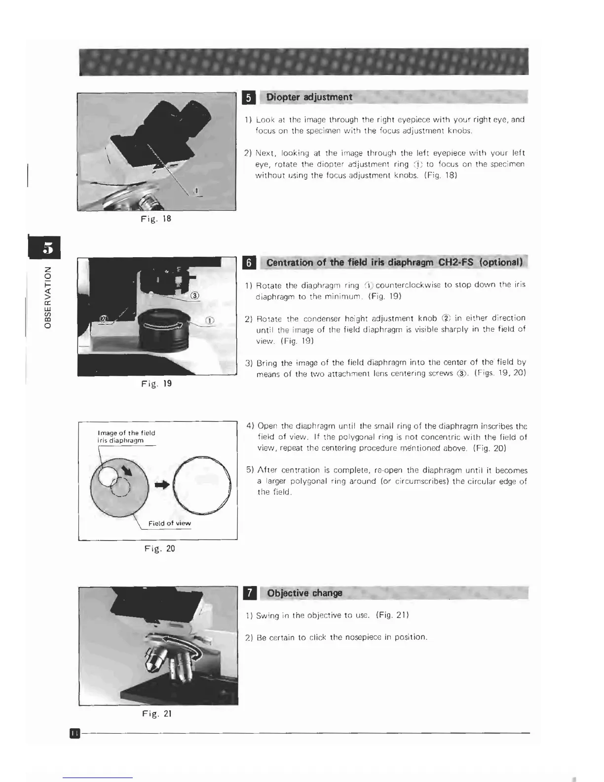
Image
of
the
field
iris
diaphragm
Field
of
view
Fig.
20
Fig,
21
III
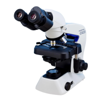
Diopter adjustment
1)
Look
at the image through the
right
eyepiece
with
your
right
eye, and
focus on the specimen
"\lith the focus
adjustnlent
knobs.
2)
Next,
looking
at the image
through
the
left
eyepiece ','.lith
your
left
eye,
rotate
the
diopter
adjustment ring
:5;
to
focus on the specimen
'Ivithout using the focus
adjustment
knobs. (Fig.
IS}
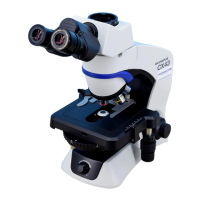
II
Centration
of
the field iris diaphragm
CH2·F~
(optional)
1)
Rotate
the diaphragm ring
C',)
counterclockwise
to
stop dO'lvn the iris
diaphragm
to
the
minimum.
(Fig. 19)
2) Rotate the condenser height
adjustment
knob
(~;
in either
direction
until
the image
of
the field diaphragm
is
viSible sharply in the
held
of
view. (Fig. 19)
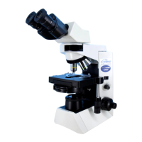
3)
Bring the image
of
the
field diaphragm
into
tile
center
of
the
field
by
means
of
the
two
attachment
lens centering screws (3). (Figs.
19,20)
4}
Open the diaphragm
until
the small ring
of
the diaphragm inscribes the
field
of
view.
If
the polygonal ring
is
not
concentric
with
the field
of
viev.;, repeat
the
centering procedure
mentioned
above. (Fig. 20)
5)
After
centration
is
complete, re-open the diaphragm
until
it becomes
a larger
polygonal
ring around (or circumscribes)
the
circular
edge
of
the field.
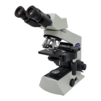
II
Objective change
I)
Swing
in
the
objective
to
use.
(Fig.21}
2)
Be
certain
to
click
the
nosepiece in
position.
11-----------------------------
 Loading...