7
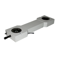
Fig. 4
Fig. 5
Fig. 6
Fig. 7
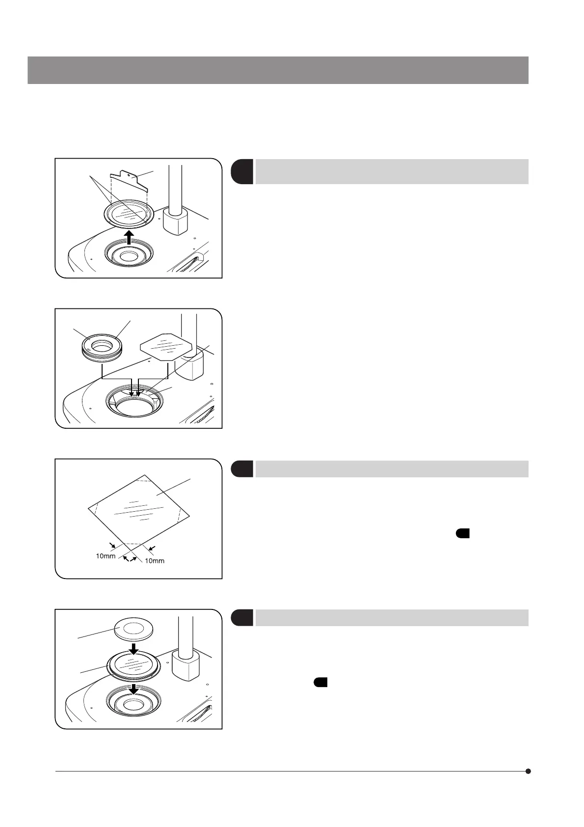
4
Changing the Illumination
Cassette Positions
(Figs. 4 & 5)
1. Insert the driver ² into the groove @ on the frame of the stage glass and
turn the frame counterclockwise to remove it.
2. Lift the “BF” and “DF” illumination cassettes by lifting them. Leave the
“Oblique” cassette in position.
3. Gently push the BF (or DF) illumination cassette ³ into the desired position
by aligning the red index | with the index ƒ on the turret.
4. Place the stage glass in the original position and clamp securely using
the driver ².
5
Attaching the Sheet Films
(Fig. 6)
}Commercially available ND and CC sheet films (75 x 75 mm) can be
attached on the illumination selector turret.
Up to two sheet films, each with thickness of 0.1 mm, can be attached.
1. Cut the four corners of each sheet film @ using a pair of scissors.
2. Remove the stage glass as described in step 1 of “
4 Changing the
Illumination Cassette Positions.”
3. Place the sheet film(s) on the desired illumination cassette by inserting
the rear side of each sheet film into the guide 7 on the turret. (Fig.5)
4. Place the stage glass in the original position.
6
Attaching the Stage Plate
(Fig. 7)
}The stage plate (the SP-FL fluorescence center plate or the SZ2-SPBW/
SP-BW2 monochrome plate) can be used in reflected fluorescent light
observation, etc.
1. Remove the stage glass using the driver using the procedure as described
in step 1 of “
4 Changing the Illumination Cassette Positions.”
2. Place the stage glass @ upside down on the stage.
3. Place the stage plate ² on the stage glass that is placed upside down.
# This installation deprives the simplified waterproof function from the
illuminator stand. If water is spilt on the stage, always be sure to
wipe it immediately.
@
²
|
³
ƒ
@
²
@
7
 Loading...