61F-G@
13
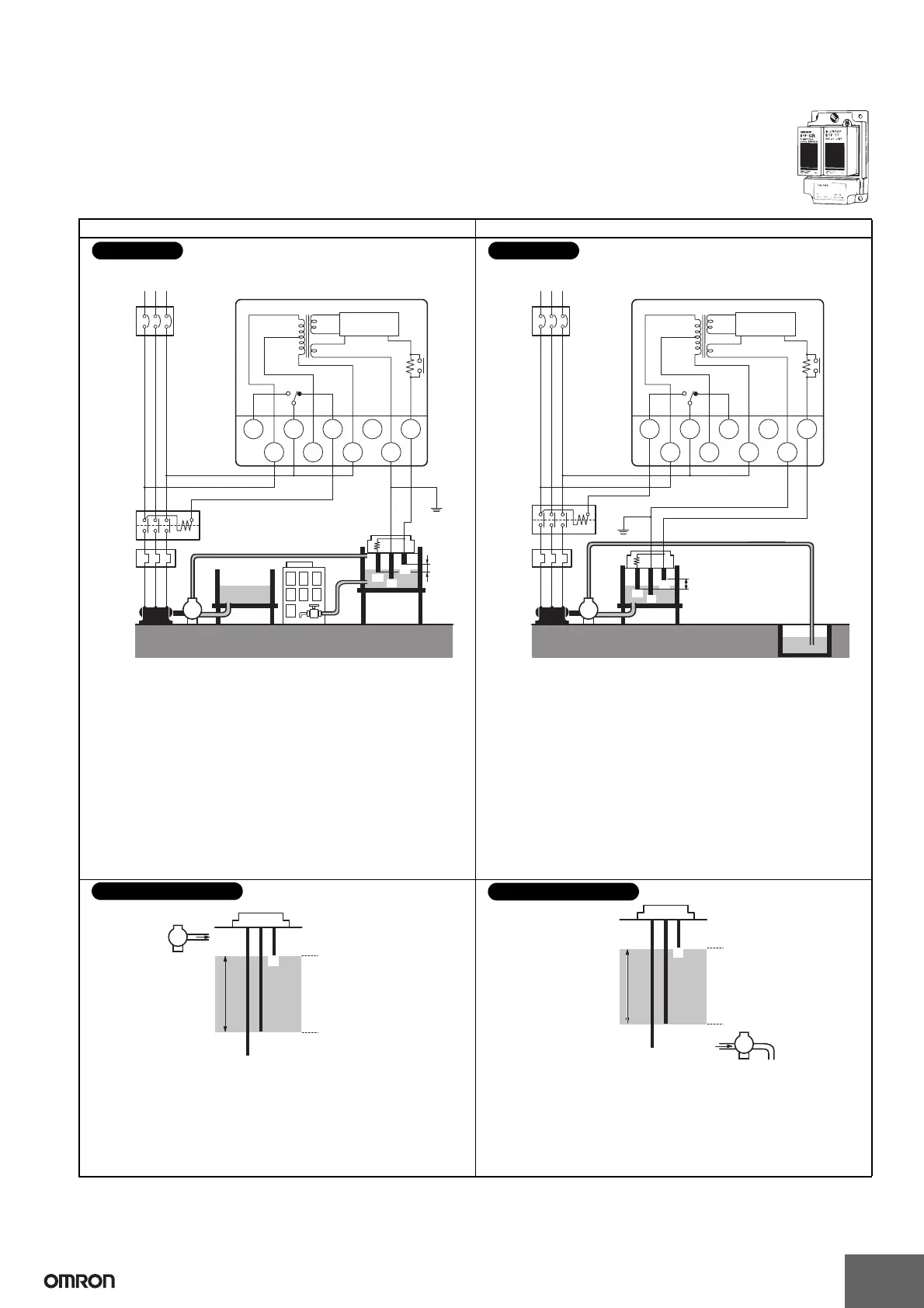
■ Two-Wire Connections
Automatic Water Supply Control Automatic Drainage Control
Basic Type
61F-GR
Automatic Water Supply and
Drainage Control
E1
R
E3
E2
U
U
U
Contactor
Water supply
source
Stop
Start
Motor
protective
relay
MCCB
RS
M
T
220-VAC power supply
61F-GR
(See
note.)
P
8 V
220 V
0 V
110 V
24 V
Water
tank
PS-3SR
S0 S2 E3S1
Tc E1TbTa
61F-11R
Relay Unit
Note: Be sure to ground the common Electrode (the longest Electrode).
• Connect Tb to the contactor’s coil terminal.
• Power Supply Connections
110 VAC: Connect S
0
and S
1
.
220 VAC: Connect S
0
and S
2
.
• With 2-wire connections, only two wires are required between
the 61F-GR and Electrode Holder, but three wires are required
for the Electrodes.
• The Electrode Holder must be specified for 2-wire connections.
(Resistance R is built into Electrode Holders for 2-Wire
Connections.)
• The Relay Unit must also be specified for 2-wire connections.
Connections
E
1
R
E
3
E
2
U
U
U
Contactor
Waste
water
tank
Reservoir
Motor
protective
relay
MCCB
RS
M
T
220-VAC power supply
61F-GR
(See
note.)
P
8 V
220 V
0 V
110 V
24 V
PS-3SR
S
0
S
2
E
3
S
1
T
c
E
1
T
b
T
a
61F-11R
Relay Unit
Stop
Start
Note: Be sure to ground the common Electrode (the longest Electrode).
• Connect Ta to the contactor’s coil terminal. (Do not connect
Tb.)
• Power Supply Connections (for models with 110/220-V power)
110 VAC: Connect S
0
and S
1
.
220 VAC: Connect S
0
and S
2
.
• With 2-wire connections, only two wires are required between
the 61F-GR and Electrode Holder, but three wires are required
for the Electrodes.
• The Electrode Holder must be specified for 2-wire connections.
(Resistance R is built into Electrode Holders for 2-Wire
Connections.)
• The Relay Unit must also be specified for 2-wire connections.
Connections
E
1
E
2
E
3
P
Water
supply
(U indicator ON)
Pump OFF
Pump ON
(U indicator OFF)
The pump stops (U indicator ON) when the water level reaches
E
1
and starts (U indicator OFF) when the water level drops below
E
2
.
Principles of Operation
E
1
E
2
E
3
Water drainage
(U indicator ON)
Pump OFF
Pump ON
(U indicator OFF)
P
The pump starts (U indicator ON) when the water level reaches
E
1
and stops (U indicator OFF) when the water level drops below
E
2
.
Principles of Operation
 Loading...