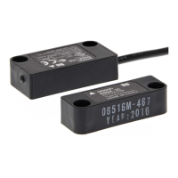
Compact Non-Contact Door Switch
INSTRUCTION MANUAL
Thank you for purchasing D40A Compact Non-contact
Door Switch. Please read and understand this manual
before using the products. Keep this manual ready to
use whenever needed. Only qualified person trained
in professional electrical technique should handle
D40A. Please consult your OMRON representative if
you have any questions or comments. Make sure that
information written in this document are delivered to
the final user of the product.
The D40A non-contact door switch provides a
safety-related interruption at a specified proximity
position of its actuator through a safety controller.
Type D40A
English
2139497-6E
Machine may start operating and may result serious
injury or death.
Do not put the actuator close to the switch when the
door is opened.
Also make sure to install D40A to minimize defeat
possibilities. For required measures, refer to ISO14119
and other relevant standards and regulations.
Safety Precautions
Meanings of Signal Words
The following signal words are used in this manual.
Alert Statements
WARNING
WARNING
Indicates a potentially hazardous
situation which, if not avoided, will
result in minor or moderate injury, or
may result in serious injury or death.
Additionally there may be significant
property damage.
(1)
Disconnect G9SX-NS from power supply when wiring D40A.
Devices connected to G9SX-NS may operate unexpectedly.
(2) Do not operate the D40A with flammable or explosive gas.
(3) Incorrect wiring may lead to loss of safety function. Wire
conductors correctly and verify the operation of D40A before
using the system in which D40A is incorporated.
(4)
Auxiliary monitoring output is NOT safety output. Do not use
auxiliary monitoring output as any safety output. Such incorrect
use causes loss of safety function of D40A and its relevant system.
(5)
After installation of D40A, qualified personnel should confirm the
installation, and should conduct test operations and
maintenance.The qualified personnel should be qualified and
authorized to secure the safety on each phases of design,
installation, running, maintenance and disposal of system.
(6)
A person in charge, who is familiar to the machine in which D40A
is to be installed, should conduct and verify the installation.
(7)
Be sure to inspect D40A daily and every 6 months. Otherwise,
serious injury may possibly occur due to the system malfunction.
(8) Do not dismantle, repair, or modify D40A. Doing so may lead to
loss of its safety functions.
(9)
Use only appropriate components or devices complying with relevant
safety standards corresponding to the required level of safety
category. Conformity to requirements of safety category is determined
as an entire system. It is recommended to consult a certification body
regarding assessment of conformity to the required safety level.
Precautions for Safe Use
(1)
D40A must be used with designated actuator (D40A-1C or -A1)
and designated controller type G9SX-NS. Before using the D40A
with any other OMRON Safety Controller, check applicability in the
Instruction Manual for the other Controller.
(2) Handle with care
Do not drop D40A to the ground or expose to excessive vibration
or mechanical shocks. D40A may be damaged and may not
function properly.
(3) Conditions of storage and usage
Do not store or use the D40A under the following conditions.
D40A may be damaged and may not function properly.
1) In direct sunlight
2) At ambient temperatures out of the range of –10 to 55°C
3) At relative humidity out of the range of 25% to 85% or under
such temperature change that causes condensation.
4) In corrosive or combustible gases
5) With vibration or mechanical shocks out of the rated values.
6) Under splashing of oil or chemicals
7) In the atmosphere containing dust, saline or metal powder.
8)
Where steel scrap or metal powder may fall directly to D40A.
(4) Use cables with length less than 100m totally to connect multiple
D40A switches. The supply voltage to D40A may decrease by the
voltage drop depending on the cable or the wiring configuration.
Check the power-supply vloltage is in the rated range.
(8) Do not use D40A in the water or continuous water exposure
environment, otherwise water may leak into D40A. (An
enclosure of IP67 rating, which D40A is rated, protects against
temporary immersion in water.)
(9) Do not use the switch or actuator as a stopper. Protect the switch
and the actuator by setting up the stopper. Separate the switch
and the actuator to a distance of 1mm or more.
(10) Install D40A actuator and switch in an appropriate distance so
that it does not create a gap accessible to the hazard.
Precautions for Correct Use
D1 D2 D3 D4
G9SX-NS202
G9SX-NSA222
Total wiring length 100m max.
(5) Disconnect G9SX-NS
from power supply when replacing D40A.
Devices connected to G9SX-NS
may operate unexpectedly.
(6)
Adhesion of solvent such as alcohol, thinner, trichloroethane or
gasoline on the product should be avoided. Such solvents make
the marking on D40A illegible and cause deterioration of parts.
(7) Do not use D40A in the magnetic field of 1.5mT or more. D40A
may not function properly.
Dimensions
6
Indicator
Two. 4.2 dia.
7.2 dia. 7.2 dia.
Cable diameter : 4
Cross section
of conductor:
0.2mm
2
(AWG24)
7.2 dia. 7.2 dia.
Two. 4.2 dia.
Actuator
Switch
(1.5) (2)48
38
20
25
13
Sensing surface
17
12
13
6
48
38
Target mark
Target mark
(150)
(46)
M12
Sensing surface
15 dia.
Sensing surface
D40A-1C015-F
Connection Example
5
D1 D2 D3 D4
G9SX-NS202
G9SX-NSA222
Black
Brown
White
Blue
Black
Brown
White
Blue
Black
Brown
White
Blue
Single switch connection
Multiple switch connection
Maximum 30 switches can be connected in series.
Note 1. Maximum auxiliary output current is 10mA.
D1 D2 D3 D4
Black
Brown
White
Blue
Yellow
G9SX-NS202
G9SX-NSA222
D40A-1C
aux. output load
*Note 1
A2
See “ 1 Detection ranges”
Ratings and Specifications
4
Ratings
Specifications and Performance
Item
Rated power consumption
Auxiliary output
D40A-1C
0.6W Max. (See Note1)
Load: 24VDC 10mA
(PNP open-collector output)
Assured
operating
and
release
distance
Ambient temperature
Ambient humidity
Degree of protection
Material
Mounting method
Terminal tightening torque
5mm min. (See Note2)
-10 to +55
°
C
(No freezing or condensation)
25 to 85%RH
Switching frequency
1Hz with G9SX-NS□
Insulation resistance
(Between all conductive parts and switch case)
(Between all conductive parts and switch case)
50Mohm Min.
(by 500VDC megger)
Dielectric strength
1000VAC for 1min
Vibration resistance
Frequency: 10 to 55 to 10Hz,
Amplitude:
0.75mm half amplitude
Mechanical shock resistance
300m/s
2
Min.
IP67
Molded PBT
M4 screws
1N•m
Relaiability data
(ISO 13849-1)
MTTFd = 100 year, DC = 60%
*This data does not include the
values of a safety controller.
Item
Rated impulse
withstand voltage
1kV
D40A-1C
OFF
ON
ON
OFF
Differential
travel
Temperature
influence
15mm max.
(See Note2)
Note1
.
Power consumption of loads is not included.
Note2.
Operating distance means the distance of sensing surfases
between switch and actuator.
See “ 1 Detection ranges”
Repeat
accuracy (max.)
±
10% of operating distance at 23
°
C
Pollution degree 3
Electromagnetic compatibility
As per IEC/EN 60947-5-3
Weight (D40A-1C5)
Switch: approx. 145 g
Actuator: approx. 20 g
Performance Level / Safety Category
The D40A together with G9SX-NS□ can construct the condition
conforming to PL=d and Category 3 required by EN ISO 13849-1
European standard.
Refer to the following link for the Safety-related characteristic data:
http://www.fa.omron.co.jp/safety_6en/
This does NOT mean that D40A and G9SX-NS
can always be used
for required category under all the similar conditions and situations.
UL does not provide UL certification for any functional safety rating
or aspects of the D40A device.
Conformity to the categories must be assessed as a whole system.
When using D40A and G9SX-NS
for safety categories, make sure
the conformity of the whole system.
Inspection & Maintenance
• Daily inspection:
1.Check every guard door to see that machine stops
when guard door is opened.
• 6-month inspection:
1. Isolate all power.
2. Check the switch and actuator for proper alignment.
3. Check terminals for proper connections.
4. Check wiring for signs of damage.
5. Before resuming normal machine operation,
check every guard door to see that machine stops
when the guard door is opened.
Troubleshooting
D40A
Light off
NS Light off
Red
Light on
NS Light off
Yellow
Light on
NS Light off
or NS Blink
Failures involving the wiring of power supply input
Check that the brown and the blue cable are correctly connected
with G9SX-NS
’s D3 terminal and terminal D4 respectively.
Installation on magnetic substance
Installation in the vicinity of magnetic source
Failures of the parts of the circuits of D40A
Failures involving the wiring of D40A input
Failures involving the wiring of D40A outputs
Failures of the parts of the circuits of D40A
G9SX-NS
Note 1. When actuator is approximated to the switch.
Expected causes of the faults Checking points and measures to take
LED indicator Note1
Failures of the parts of the circuits of D40A Replace with a new D40A
Install the switch and actuator on a non-magnetic material.
Install D40A separate from a strong magnetic source.
Replace with a new D40A
Check that the white cable is correctly connected with G9SX-NS
’s D1 terminal.
Check that the black cable is correctly connected with G9SX-NS
’s D2 terminal.
Replace with a new D40A
Wiring
Signal Name Cable color
brown
blue
+
-
white
black
yellow
Non-contact door
switch power input
Non-contact door switch
signal input
Non-contact door switch output
Auxiliary monitoring output
(PNP open corrector output)
Description of operation
Power supply for D40A.
Connect to D3 terninal and D4 terminal on G9SX-NS
.
Input designated signal from G9SX-NS
.
To set non-contact door switch output in ON state, non-contact door
switch input must be in ON state.
Output status depends on actuator status and non-contact door switch
input state.
Output when sensor detect actuator.
Pim number
1
3
2
4
5
(15) Wiring
1.
Use the following to wire to G9SX-NS
-Solid wire: 0.2 to 2.5mm
2
AWG24 to AWG12
-Stranded wire: 0.2 to 2.5mm
2
AWG22 to AWG12
2.
When auxiliary o ut p u t is n ot u se d, cu t off t h e wiring and
protect by taping so that it does not contact other terminals.
3.
When you use an additional cable of 20m or longer,
use a multiconductor cable to group the white, black,
brown, and blue lines together.
(16) Handle cables with care:
1
)
For bending cables, it is recommended to bend them with a
radius of bend no less than six times the cable outer diameter.
2
)
Do not apply a t ensile strengt h of 50N or great er t o the cables.
(17)
In a residential environment, this product may cause radio
interference, in which case the user may be required to
take adequate measures.
(18) If there is any machine that has a large surge current(e.g.,
a motor) near D40A, connect a surge absorber to D40A
between the blue and the other lines (white, black, brown,
and yellow), respectively.
Suggested surge absorber's specification is as follows:
-Peak pulse power: 600W (10/1000μs) o r more
(Per IEC61000-4-5(surge immunity))
-Breakdown voltage: 27-33V
Note1. The operating distance is the distance between the switch and
actuator sensing surfaces.
Note2. The graph indicates shifting to X or Z direction from following
condition that the switch and actuator target marks are on the same
axis and the sensing surfaces are exactly parallel condition.
Dashed lines indate reference value for maximum and minimun
oprating distance at abient temperature +23°C. The solid line indicates
reference values of the maximum and minimum operating distances.
Switch and actuator operation
2
Switch and Actuator Mounting Directions
Switch and Actuator Operating Directions
Switch
Actuator
Switch
Actuator
Detection Ranges (Engineering data)1
(11) Where two or more switches mounted adjacent, they should be
no closer than 25mm.
(12) Check that the machine is stopped whenever the interlocked
guard door is open.
25mm Min.
(13) Do not mount the switch and actuator on magnetic materials,
otherwise it may affect the operating distance.
Refer to the chart below for the estimated influence.
(14) Tighten each screw with specified torque by using M4 screw
and washer for the installation of the switch and actuator. After
installation and commissioning, the actuator and switch fixing
screws should be coated with tamper proof varnish or similar
compound.Using anaerobic locking compounds can have a
detrimental effect on the plastic switch case if the compounds
contact with the switch case.
Switch
Actuator
Distance from
magnetic materials
Operating distance
Approximately 90% of the original value
No influence
0 to 5mm
5mm Min.
9.5
Declaration of Conformity
Safety Standards
Instructions in the EU languages and a signed EU Declaration
of Conformity are available on our website at
http://www.industrial.omron.eu/safety.
D40A is designed and manufactured in accordance with
the following standards:
EN ISO13849-1:2015
Cat. 3 PL d
(with G9SX-NS
)
,
IEC/EN61508 SIL3 (with G9SX-NS),
IEC/EN60947-5-3 PDDB
(with G9SX-NS),
IEC/EN61000-6-4, ISO14119 (Low level coded),
UL508, CAN/CSA C22.2 No.14
Original instructions
LED Display
LED color
Status
Sensor does NOT detect actuator
Sensor detect actuator
RED
YELLOW
Suitability for Use
Omron Companies shall not be responsible for conformity with any standards,
codes or regulations which apply to the combination of the Product in the
Buyer’s application or use of the Product. At Buyer’s request, Omron will
provide applicable third party certification documents identifying ratings and
limitations of use which apply to the Product. This information by itself is not
sufficient for a complete determination of the suitability of the Product in
combination with the end product, machine, system, or other application or
use. Buyer shall be solely responsible for determining appropriateness of the
particular Product with respect to Buyer’s application, product or system.
Buyer shall take application responsibility in all cases.
NEVER USE THE PRODUCT FOR AN APPLICATION INVOLVING SERIOUS
RISK TO LIFE OR PROPERTY OR IN LARGE QUANTITIES WITHOUT
ENSURING THAT THE SYSTEM AS A WHOLE HAS BEEN DESIGNED TO
ADDRESS THE RISKS, AND THAT THE OMRON PRODUCT(S) IS
PROPERLY RATED AND INSTALLED FOR THE INTENDED USE WITHIN
THE OVERALL EQUIPMENT OR SYSTEM.
OMRON Corporation (Manufacturer)
Contact: www.ia.omron.com
Regional Headquarters
Shiokoji Horikawa, Shimogyo-ku, Kyoto, 600-8530 JAPAN
OMRON EUROPE B.V. (Importer in EU)
Wegalaan 67-69, 2132 JD Hoofddorp
The Netherlands
Tel: (31)2356-81-300/Fax: (31)2356-81-388
OMRON ELECTRONICS LLC
2895 Greenspoint Parkway, Suite 200
Hoffman Estates, IL 60169 U.S.A.
Tel: (1) 847-843-7900/Fax: (1) 847-843-7787
OMRON ASIA PACIFIC PTE. LTD.
438B Alexandra Road, #08-01/02
Alexandra Technopark,
Singapore 119968
Tel: (65) 6835-3011/Fax: (65) 6835-2711
OMRON (CHINA) CO., LTD.
Room 2211, Bank of China Tower,
200 Yin Cheng Zhong Road,
PuDong New Area, Shanghai, 200120, China
Tel: (86) 21-5037-2222/Fax: (86) 21-5037-2200
ON OFF
Unstable
range
15mm (point B) 5mm (point A)
Y-direction movement
X
Y
16
14
12
10
8
6
4
2
0
6 4 20 2 4 6
Distance from the target mark on the switch X (mm)
Operating distance Y (mm)
Sensing
surface
Target marks
Engineering Data
(OFF to ON)
Maximum
operating distance
(ON to OFF)
18
B
A
15 10 50 51015
Distance from the target mark on the switch Z (mm)
Operating distance Y (mm)
18
16
14
12
10
8
6
4
2
0
Z
Y
Sensing
surface
Target marks
Engineering Data
(OFF to ON)
Maximum
operating distance
(ON to OFF)
B
A
Internal Circuit
brown / 1
white / 2
black / 4
yellow / 5
blue / 3
Internal connection
3
5
3
2
4
1
Engineering Data
(ON to OFF)
Minimum
operating distance
(OFF to ON)
OFF range
ON range
ON range
OFF range
Engineering Data
(ON to OFF)
Minimum
operating distance
(OFF to ON)
© OMRON Corporation 2010-2022 All Rights Reserved.
OMRON declares that D40A is in conformity with the requirements
of the following EU Directives and UK Legislation:
EU:
Machinery Directive 2006/42/EC, EMC Directive 2014/30/EU,
RoHS Directive 2011/65/EU
UK:
2008 No. 1597 Machinery (Safety), 2016 No. 1091 EMC,
2012 No. 3032 RoHS