61F-G@
9
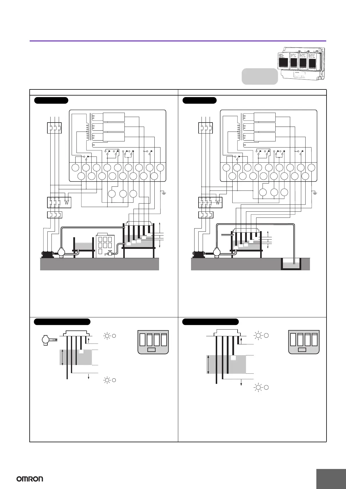
Automatic Water Supply with Abnormal Water Increase and Water Shortage Alarms Automatic Drainage Control with Abnormal Water Increase and Water Shortage Alarms
Basic Type
61F-G3
Dimensions:
page 14
Automatic Water Supply and Drainage
Control with Abnormal Water Increase and
Water Shortage Alarms
8 V
U
1
U
2
U
3
U
1
U
2
U
3
U
1
U
3
U
2
Contactor
Water
supply
source
Motor
protection
relay
MCCB
RS
M
T
220 VAC power supply
61F-G3
Water
tank
PS-5S
(See
note.)
T
a
T
c
T
b
B
1
B
2
L
c
E
1
E
3
E
5
S
0
S
1
S
2
LH LL
PLPLB
E
2
E
4
E
4
E
5
P
24 V
24 V
61F-11
Relay Unit
24 V
61F-11
Relay Unit
Alarm
Full tank
Upper
limit
Lower
limit
220 V
110 V
0 V
61F-11
Relay Unit
Water
shortage
E
3
Stop
Start
E
2
E
1
Note: Be sure to ground the common Electrode (the longest Electrode).
• Connect Tb to the contactor’s coil terminal.
• Power Supply Connections
110 VAC: Connect S
0
and S
1
.
220 VAC: Connect S
0
and S
2
.
Connections
8 V
U
1
U
2
U
3
U
1
U
2
U
3
U
1
U
3
U
2
Contactor
Waste
water
tank
Reservoir
Motor
protection
relay
MCCB
RS
M
T
220 VAC power supply
61F-G3
PS-5S
(See
note.)
T
a
T
c
T
b
B
1
B
2
L
c
E
1
E
3
E
5
S
0
S
1
S
2
LH LL
PLPLB
E
2
E
4
E
4
E
5
P
24 V
24 V
61F-11
Relay Unit
24 V
61F-11
Relay Unit
Alarm
Upper
limit
220 V
110 V
0 V
61F-11
Relay Unit
Lower
limit
Full tank
Water shortage
Start
Stop
E
3
E
2
E
1
Note: Be sure to ground the common Electrode (the longest Electrode).
• Connect Ta to the contactor’s coil terminal. (Do not connect
Tb.)
• Power Supply Connections
110 VAC: Connect S
0
and S
1
.
220 VAC: Connect S
0
and S
2
.
Connections
E
1
E
2
E
3
E
4
E
5
P
Water
supply
Upper
limit
Lower
limit
(U
1
indicator ON)
Pump OFF
Pump ON
(U
2
indicator ON)
(U
3
indicator OFF)
(U
2
indicator OFF)
B
L
H
L
L
B
• The pump stops (U
2
indicator ON) when the water level
reaches E
2
and starts (U
2
indicator OFF) when the water level
drops below E
3
.
• If the water level rises to E
1
for any reason, the upper-limit
indicator turns ON and the alarm sounds (U
1
indicator ON).
If the water level drops below E
4
for any reason, the lower-limit
indicator turns ON and the alarm sounds (U
3
indicator OFF).
Relay Unit Locations
Principles of Operation
E1
E3
E4
E5
Upper
limit
Lower
limit
Pump ON
Pump OFF
(U
1
indicator ON)
(U
2
indicator ON)
(U
2
indicator OFF)
(U
3
indicator OFF)
B
L
H
B
L
L
E2
• The pump starts (U
2
indicator ON) when the water level
reaches E
2
and stops (U
2
indicator OFF) when the water level
drops below E
3
.
• If the water level rises to E
1
for any reason, the upper-limit
indicator turns ON and the alarm sounds (U
1
indicator ON).
If the water level drops below E
4
for any reason, the lower-limit
indicator turns ON and the alarm sounds (U
3
indicator OFF).
Relay Unit Locations
Principles of Operation
 Loading...