A22LK
6
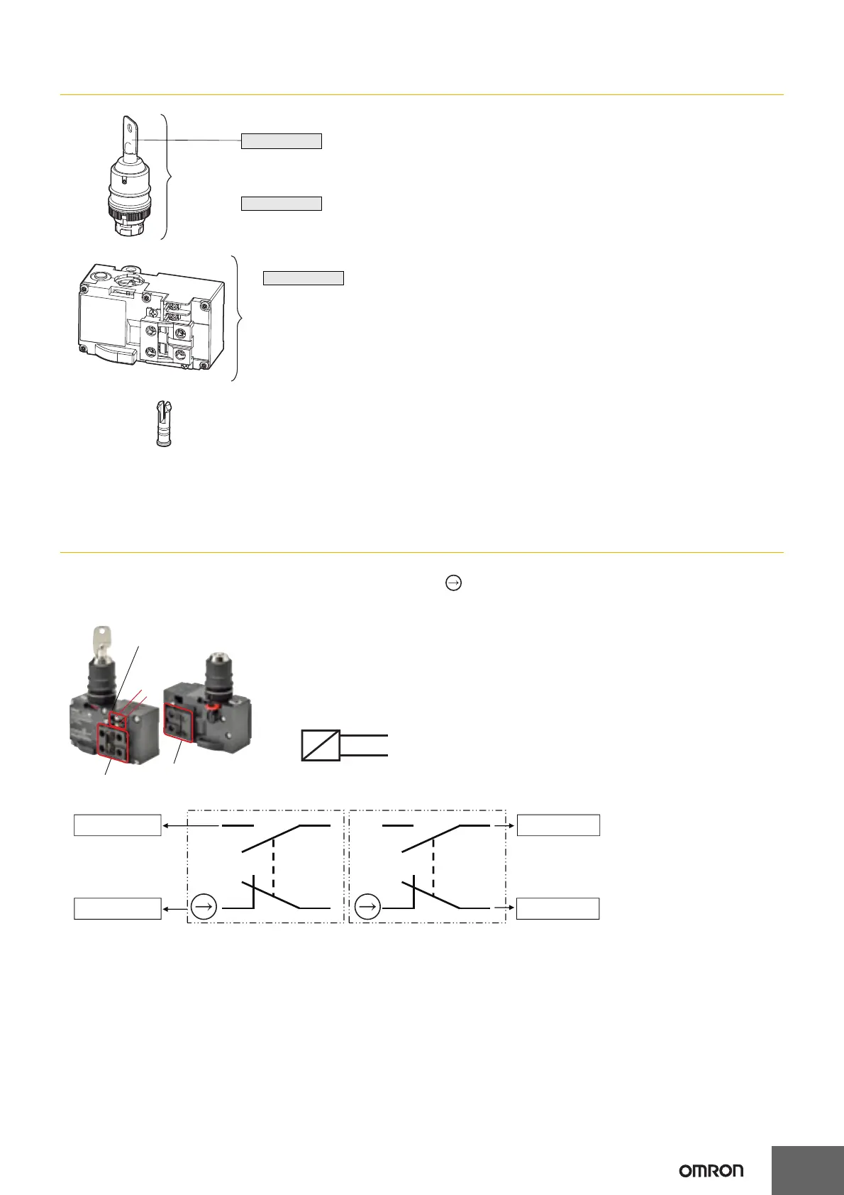
Structure and Nomenclature
Connection
Internal Circuit Diagram
• Direct opening contacts used as safety-circuit input are indicated with the mark.
• The solenoid has no polarity.
Contact Ratings
3A at 240 VAC (resistive load)
0.27A at 250 VDC (resistive load)
Contact Configuration
2NC/2NO
Switch Unit
Lock Pin
Attached with the Switch to prevent the operation unit from coming off the switch unit.
(Refer to "Lock pin" on page 9 for use.)
(The above figures are examples of the model with key.)
Key
* Two keys are provided.
Operation Unit
Switch A
Switch B
Solenoid terminals
Note. The solenoid terminals have no polarity.
Switch A
Switch B
To control circuit To control circuit
To safety circuit To safety circuit
13
14
31
32
13
14
31
32
13
31
13
31
14
32
14
32
E1
E2
E1
E2
DC24V ±
Solenoid
terminals
10%
 Loading...