14
2-1-3 I/O Connecting Cable
The first Expansion I/O Rack is connected to the CPU Rack, and the second and
third Expansion I/O Racks are connected to the previous Expansion I/O Rack
through I/O Connecting Cable. There are five different lengths of cable avail-
able, which can be used as desired to provide the desired distance between
each Rack. The sum of the lengths of all the I/O Connecting Cables connected
within one PC, however, but be 12 m or less.
Model Cable length
C200H-CN311 30 cm
C200H-CN711 70 cm
C200H-CN221 2 m
C200H-CN521 5 m
C200H-CN131 10 m
2-2 Units
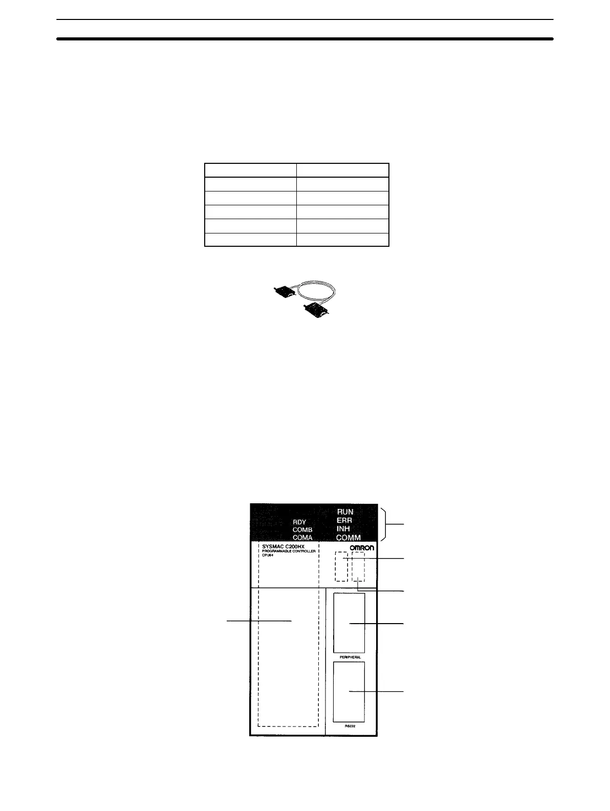
2-2-1 CPU Units
The following diagram shows the components of the CPU Unit as viewed from
the front cover. The numbers in the diagram correspond to the numbers of the
following items in the description.
1. Indicators
2. Memory Casette
compartment
4. Peripheral port
5. RS-232C port
3. DIP Switch
6. Communications Board
compartment
Units
Section 2-2

 Loading...


