71
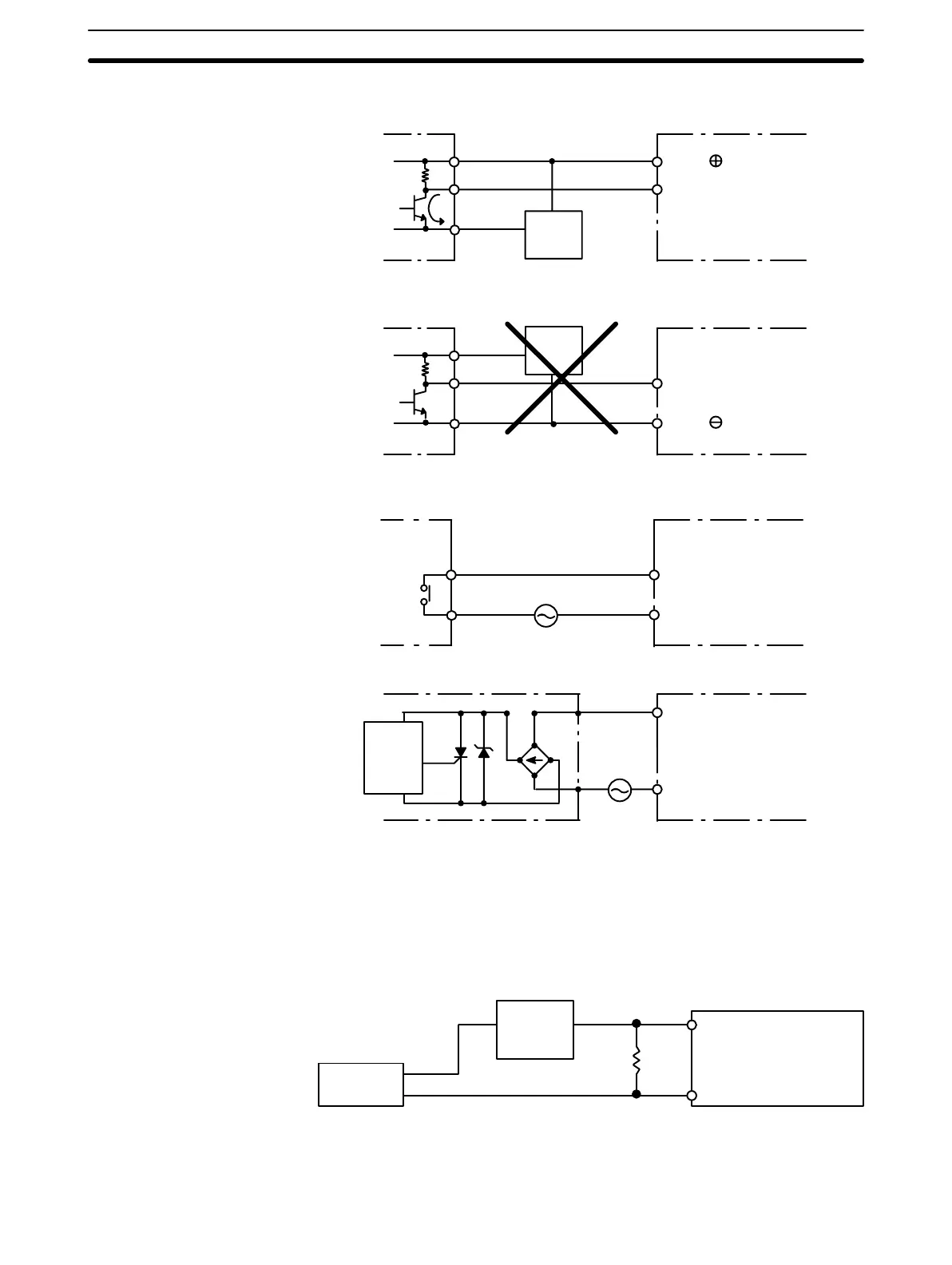
The circuit below should be used for I/O devices having a voltage output.
0 V
Output
+
COM
Voltage output
Sensor
Power
Supply
IN DC Input Unit
The circuit below should NOT be used for I/O devices having a voltage output.
0 V
Output
+
COM
Voltage output
IN DC Input Unit
Sensor
Power
Supply
AC Input Units
COM
Contact output
IN AC Input Unit
COM
AC Switching
IN AC Input Unit
Prox-
imity
switch
main
circuit
Note When using Reed switch as the input contact for an AC Input Unit, keep the
allowable current to 1 A or greater. If Reed switches with smaller allowable cur-
rents are used, the contacts may fuse due to surge currents.
Input Leakage Current When two-wire sensors, such as photoelectric sensors, proximity sensors, or
limit switches with LEDs, are used, the input bit may be turned ON erroneously
by leakage current. In order to prevent this, connect a bleeder resistor across the
input as shown below.
Sensor
Input
power
supply
Bleeder
resistor
R
PC
If the leakage current is less than 1.3 mA, there should be no problem. If the leak-
age current is greater than 1.3 mA, determine the resistance (R) and power rat-
ing (W) for the bleeder resistor using the following formulas.
Wiring
Section 3-2

 Loading...


