76
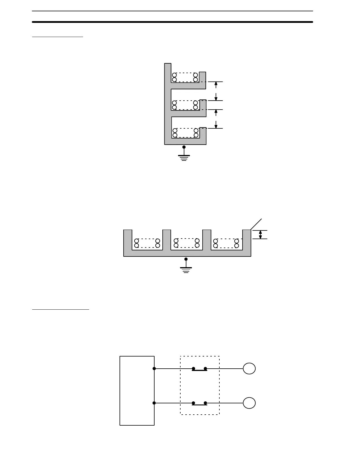
External Wiring
If power cables must be run alongside the I/O wiring (that is, in parallel with it), at
least 300 mm must be left between the power cables and the I/O wiring as shown
below.
Low current cable
Control cable
Power cable
300 mm min.
300 mm min.
1
2
3
Class-3 ground
Where: 1 = I/O wiring
2 = General control wiring
3 = Power cables
If the I/O wiring and power cables must be placed in the same duct (for example,
where they are connected to the equipment), they must be shielded from each
other using grounded metal plates.
Metal plate (iron)
123
200 mm min.
Class-3 ground
Where: 1 = I/O wiring
2 = General control wiring
3 = Power cables
Interlock Circuits
When the PC controls an operation such as the clockwise and counterclock-
wise operation of a motor, provide an external interlock such as the one
shown below to prevent both the forward and reverse outputs from turning
ON at the same time.
PC
MC2
MC1
00501
00502
MC1
MC2
Motor clockwise
Motor counterclockwise
Interlock circuit
Wiring
Section 3-2

 Loading...


