238
Components and Switch Settings Section 6-3
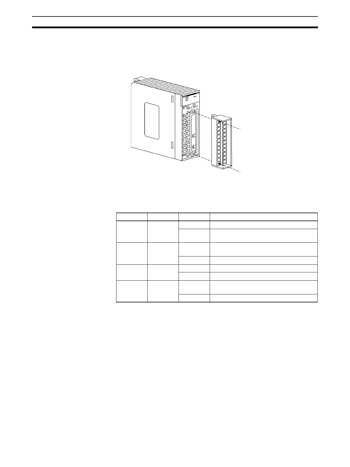
The terminal block is attached by a connector. It can be removed by loosening
the two black mounting screws located at the top and bottom of the terminal
block.
Check to be sure that the black terminal block mounting screw is securely
tightened to a torque of 0.5 N·m.
6-3-1 Indicators
The indicators show the operating status of the Unit. The following table
shows the meanings of the indicators.
Fasten the mounting screw.
Fasten the mounting screw.
LED Meaning Indicator Operating status
RUN
(green)
Operating Lit Operating in normal mode.
Not lit Unit has stopped exchanging data with the
CPU Unit.
ERC (red) Error
detected by
Unit
Lit Alarm has occurred (such as disconnection
detection) or initial settings are incorrect.
Not lit Operating normally.
ADJ (yel-
low)
Adjusting Flashing Operating in offset/gain adjustment mode.
Not lit Other than the above.
ERH (red) Error in the
CPU Unit
Lit Error has occurred during data exchange
with the CPU Unit.
Not lit Operating normally.
 Loading...


