7 High-speed Counters
7-48
CJ2M CPU Unit Pulse I/O Module User’s Manual
z Specifications and Operation
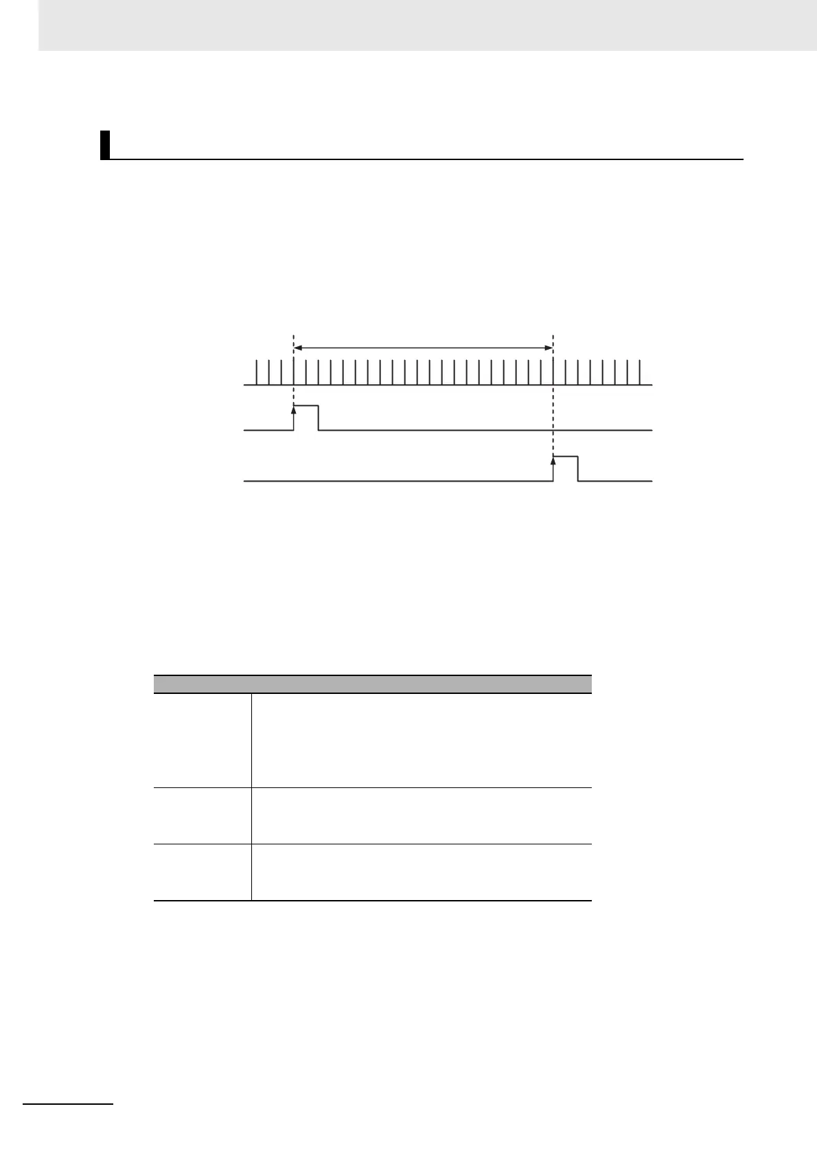
The number of encoder pulse inputs is counted with high-speed counter input 1. Sensor inputs 1
and 2 are read as interrupt inputs at terminals IN00 (CIO 2960.00) and IN01 (CIO 2960.01). The
workpiece length is measured by the number of pulses counted between an ON input at sensor
input 1 and an ON input at sensor input 2.
The program finds the difference between the high-speed counter PVs that are latched for interrupt
inputs IN00 and IN01 and outputs the difference to D10.
z Applicable Instructions
MSKS(690) instruction:Enables I/O interrupts.
INI(880) instruction:Changes high-speed counter PVs. (Clears them to 0.)
z Preparations
• PLC Setup
The high-speed counter inputs and interrupt inputs are set in the PLC Setup.
Length Measurement (Using Interrupts to Read Input Pulses)
PLC Setup
High-speed
counter 1
Counter setting: Input pulse frequency (100 kHz max.)
Counting Mode: Linear mode
Reset Method: Z phase, software reset
Comparing After Counter Reset: Stop
Pulse Input Mode: Differential Phase (x4)
IN00 Input Operation: Interrupt
Edge: Rising Edge
Latch: High-speed counter 1
IN01 Input Operation: Interrupt
Edge: Rising Edge
Latch: High-speed counter 1
PV A latched.
PV B latched.
High-speed counter 1
Sensor input 1
Interrupt input 0:
CIO 2960.00
Sensor input 2
Interrupt input 1:
CIO 2960.01
Workpiece length (PV B − PV A)
 Loading...


