2-7
2 I/O Application Procedures and Function Allocations
CJ2M CPU Unit Pulse I/O Module User’s Manual
2-2 Allocating I/O Functions
2
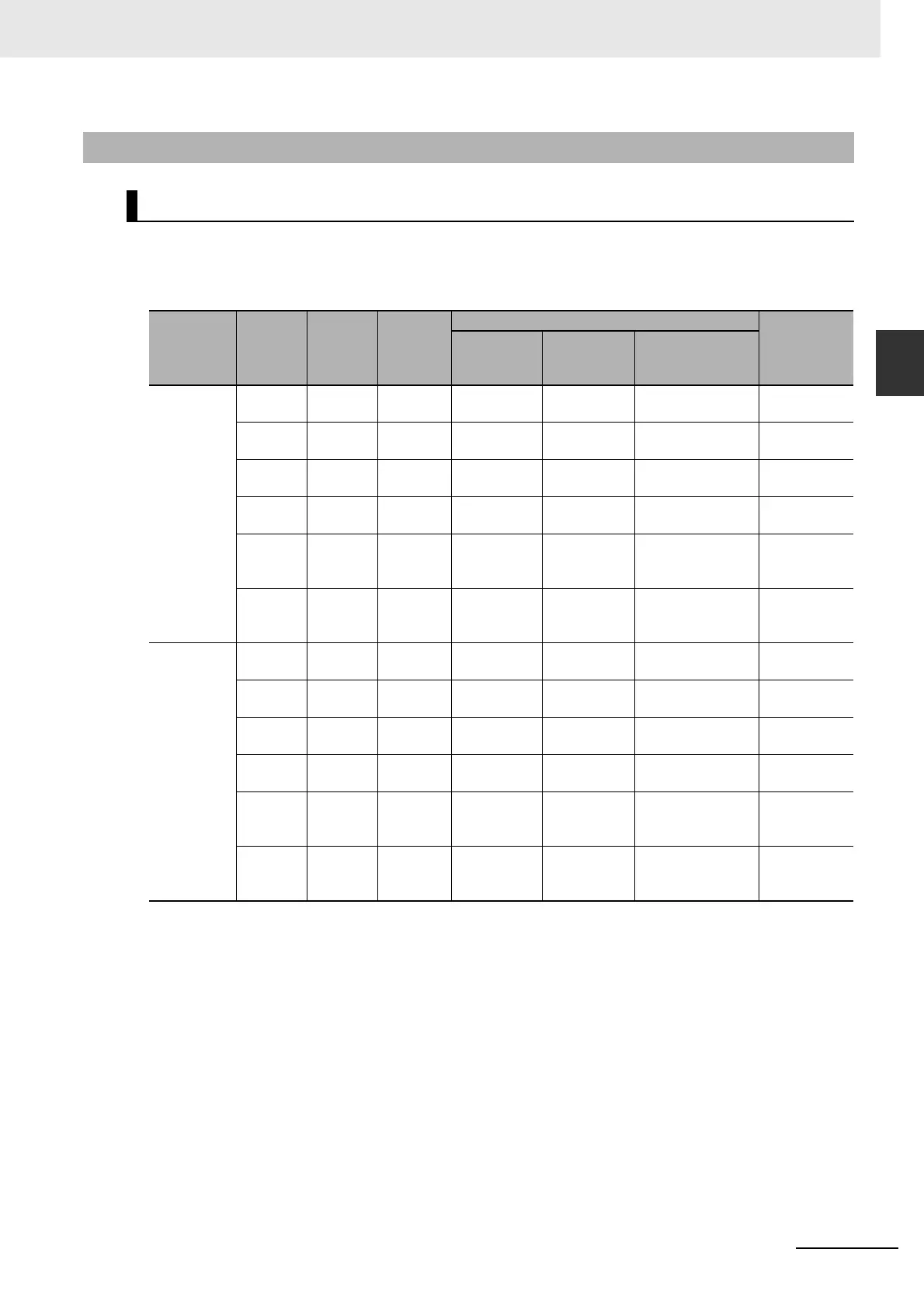
2-2-4 Allocating Functions to Output Terminals
Functions are assigned to output terminals when an instruction is executed for an output bit. (The
instructions that can be used include OUT, ORG(889), and PWM(891).) If the origin search operation is
set to mode 1 or mode 2 in the PLC Setup, PWM outputs cannot be used for the output terminals that
are used for error counter reset outputs.
* The pulse output method is specified with an operand in the Pulse Output Instruction.
2-2-4 Allocating Functions to Output Terminals
Allocating Functions to Output Terminals
Pulse I/O
Module
No.
Output
terminal
symbol
Bit
address
Normal
outputs
Pulse outputs*
PWM output
CW/CCW
outputs
Pulse +
direction
outputs
Origin search
output
0 (on the
right)
OUT00 CIO
2961.00
Normal
output 0
CW pulse
output 0
Pulse out-
put 0
--- ---
OUT01 CIO
2961.01
Normal
output 1
CCW pulse
output 0
Pulse out-
put 1
--- ---
OUT02 CIO
2961.02
Normal
output 2
CW pulse
output 1
Direction
output 0
--- ---
OUT03 CIO
2961.03
Normal
output 3
CCW pulse
output 1
Direction
output 1
--- ---
OUT04 CIO
2961.04
Normal
output 4
--- --- Pulse output 0
error counter
reset output
PWM output
0
OUT05 CIO
2961.05
Normal
output 5
--- --- Pulse output 1
error counter
reset output
PWM output
1
1 (on the
left)
OUT10 CIO
2963.00
Normal
output 6
CW pulse
output 2
Pulse out-
put 2
--- ---
OUT11 CIO
2963.01
Normal
output 7
CCW pulse
output 2
Pulse out-
put 3
--- ---
OUT12 CIO
2963.02
Normal
output 8
CW pulse
output 3
Direction
output 2
--- ---
OUT13 CIO
2963.03
Normal
output 9
CCW pulse
output 3
Direction
output 3
--- ---
OUT14 CIO
2963.04
Normal
output 10
--- --- Pulse output 2
error counter
reset output
PWM output
2
OUT15 CIO
2963.05
Normal
output 11
--- --- Pulse output 3
error counter
reset output
PWM output
3