6
Serial Communications Settings
6.2. Cable Wiring
Refer to SECTION 3 Installation and Wiring of the CJ Series Serial Communications Units
OPERATION MANUAL (Cat. No. W336) for details on cable wiring.
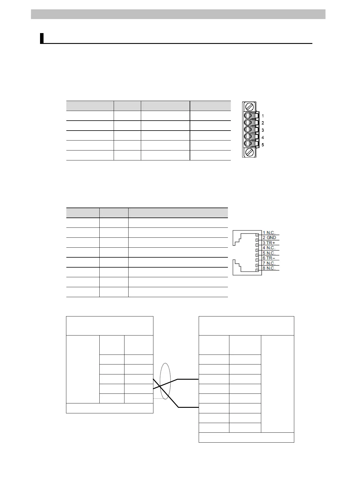
Check connector configuration and pin assignments before wiring.
■Connector configuration and pin assignments
CJ1W-SCU42 Serial Communications Unit applicable connector: Terminal block
1(See note 1.) RDA Receive data - Input
2(See Note 1.) RDB Receive data + Input
3(See Note 1.) SDA Send data - Output
4(See Note 1.) SDB Send data + Output
5(See Note 2.) FG Shield -
Note 1: For 2-wire connection, use either pins 1 and 2 or pins 3 and 4.
Note 2: Pin 5 (Shield) is connected to the GR terminal on Power Supply Unit though Serial
Communications Unit. The cable shield can thus be grounded by grounding the GR
terminal of Power Supply Unit.
Oriental Motor BLED3AM-R (CN7/CN8) applicable connector: RJ-45
Pin No. Symbol Description
1 N.C. Not used
2 GND GND
3 TR+ RS-485 communication signal (+)
4 N.C. Not used
5 N.C. Not used
6 TR- RS-485 communication signal (-)
8 N.C. Not used
■Cable/Pin assignments
Serial Communications Unit
(CJ1W-SCU42)
Driver
(BLED3AM-R)
RS-422A/
485
interface
Signal
name
Pin No. Pin No. Signal
name
RS-485
interface
RDA- 1 1 -
RDB+ 2 2 GND
SDA- 3 3 TR+
SDB+ 4 4 -
FG 5 5 -
Terminal block connector 6 TR-
7 -
8 -
RJ-45 connector

 Loading...


